Chapter 2 Performance Verification Test RIGOL
DS6000 Performance Verification Guide
Bandwidth Limit Test
The bandwidth limit test verifies the 20 MHz bandwidth limit function and 250 MHz bandwidth limit
function of the oscilloscope respectively by testing the amplitude losses of the oscilloscope under test
at the bandwidth limits.
Specification
Bandwidth Limit
Amplitude Loss
[1]
-3 dB to 1 dB
Note
[1]
: Amplitude Loss (dB) = 20 × lg (Vrmsn/Vrms1). Wherein, Vrmsn represents Vrms2 or Vrms3; Vrms1 is the
measurement result of the amplitude effective value at 1 MHz; Vrms2 is the measurement result of the amplitude
effective value at the bandwidth limit; Vrms3 is the measurement result of the amplitude effective value when the
frequency is greater than the bandwidth limit.
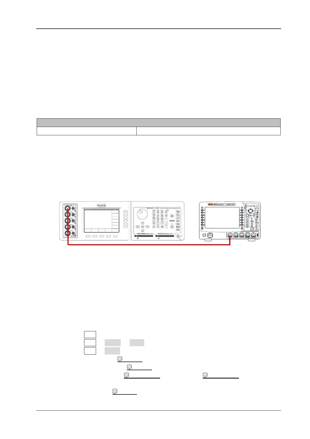
Test Connection Diagram
Figure 2-4 Bandwidth Limit Test Connection Diagram
Test Procedures
1. 20 MHz Bandwidth Limit Test
1) Connect the active signal terminal of Fluke 9500B to CH1 of the oscilloscope, as shown in
the figure above.
2) Enable Fluke 9500B and set its impedance to 50 Ω.
3) Configure the oscilloscope:
a) Press CH1 in the vertical control area (VERTICAL) at the front panel to enable CH1.
b) Press CH1 Probe Ratio to set the probe attenuation ratio to “1X”.
c) Press CH1 Input to set the input impedance to 50 Ω.
d) Rotate VERTICAL SCALE to set the vertical scale to 200 mV/div.
e) Rotate HORIZONTAL SCALE to set the horizontal time base to 500 ns.
f) Press HORIZONTAL POSITION and VERTICAL POSITION respectively to
set the horizontal position and vertical position to 0.
g) Press TRIGGER LEVEL to set the trigger level to 0 V.
Fluke 9500B
DS6000
 Loading...