33
SECTION 1 • BASICS
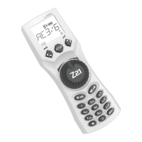
CONNECTING THE
multi
MAUS
Fig. 2 on page 61 shows the basic connection. For a fully-functional ROCO digital system with the
multi
MAUS, you will need the following components:
– A 10764 amplifier,
– A 10725 transformer,
– And a 61190 feeder track. If you are using another feeder track or system, make sure that there is no
capacitor in the feeder track.
You will find information on other devices which you can use with the
multi
MAUS in the chapter “COMPAT-
IBILITY OF THE
multi
MAUS” in the third section of this manual.
Please pay attention to the following instructions before you start connecting components:
The warranty will be voided if you are using ROCO components together with components from other
companies. In addition there is a risk of damage or malfunction to your digital system. Your warranty
will also be void if you open the housing of the
multi
MAUS.
Please only carry out any connection work with the operating voltage switched off (as an exception:
connection of further X-Bus based equipment, see below). Work carefully and make sure to avoid short
circuits at all costs when connecting to the track system. An incorrect connection may destroy the digital
components. You should also seek the advice of a specialist or local dealer.
To operate the digital system without faults, you should avoid extending the connecting cable to the
master mouse.
It is imperative that you do not connect a normal transformer on the same circuit parallel to the digital
controller. This could destroy the digital booster!
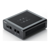
1. Plug the feeder track cable into the track socket “Track Out” on the amplifier.
2. Plug the hollow plug, which is connected to the transformer by the two-pin cable, into the “Power
In” socket.
3. Connect the
multi
MAUS and the amplifier using the cable included with your system. Plug the cable
into the connection socket on the booster labeled “Master”.
4. You can now (and not beforehand) connect the transformer to the mains socket. This way you avoid
damaging the digital system.
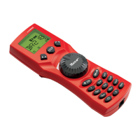
The socket labeled “slave” is for connecting a further
multi
MAUS, a Lokmaus 2 / R3, the RouteControl
10772 or a PC with the ROCOMOTION software. In this case you should have switched the system on. This
ensures that the automatic allocation of the X-Bus addresses will be without any problems. If more than
one of these devices are to be connected, you will require the data BUS distributor 10758.
If you use a Lokmaus 2 / R3 as a master, you will be unable to use some of the functions performed by a
multi
MAUS set as a slave. We therefore recommend that you use a
multi
MAUS as the master. See also
the chapter “MASTER-AND-SLAVE PRINCIPLE” in the third section of this manual.
Note on the instructions
Text that contains an “” before a word refers to a definition in the “GLOSSARY” in section three.
“+” in the diagrams means that both the keys mentioned must be pressed together.
“/” in the diagrams stands for a selection of one of the two keys mentioned.
 Loading...