The Z21
is a FLEISCHMANN and ROCO innovation.
37
English
The white “Program” LED will then ash regularly for a brief time.
The switch decoder is then in “Conguration mode”. It does not matter for the POM programming, incidentally, whether option
1, 2 or 3 is active.
2. You can now congure the switch decoder by using a wlanMAUS, multiMAUS or another input device of your choice to write a
CV variable via POM to the pseudo “loco address” 9836.
TIP: For multiMAUS and wlanMAUS, rst select the loco address 9836 as well as the POM programming mode, before the POM
programming:
Where applicable, SHIFT+MENU LOCO MODE ADDRESS OK STOP
SHIFT+OK numbers 9 8 3 6 OK
SHIFT+MENU PROGRAM MODE POM OK STOP
TIP: In the current Z21 APP (2019), the POM programming for loco decoder can be found under “CV programming”
“Manual” “Program On Main”.
3. As soon as the POM write command has been notied of a valid CV by the switch decoder, the new value is applied and con-
guration mode is exited automatically. The white LED goes out and the blue LED indicates normal mode.
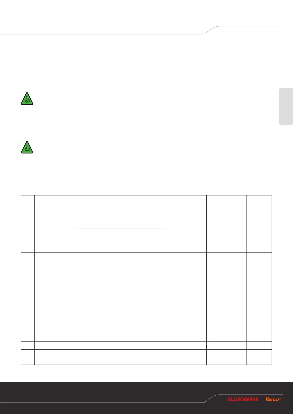
6.2.3 CV list
CV Description Range Default
#1
First decoder address, lower 6 bits (bits 0 - 5)
Together with CV #9, this generates the rst decoder address for outputs 1 to 4.
This CV can only be read. You can change the decoder addresses via the programming
button. See section Option 1 – Program addresses for outputs 1 to 8.
INFORMATION: Ensure that the decoder address is never confused with the resultant
turnout numbers. The turnout numbers and CV values can be calculated from the decoder
address, but the process is rather complicated and is described in more detail in the Rail-
Community standards RCN-213 and RCN-225.
1 – 63
read only
#3 Time output 1 active
0 = instantaneous operation similar to k83
After receiving an activation command for an output, this remains active until the control
centre sends the deactivation command. For the Z21, this means that the output remains
active, such as when the button on the multiMAUS is pressed.
Similar to operating mode 3, see CV #41 to #48.
WARNING: Some control centres from other manufacturers do not send any deactivation
commands. The correct functioning of instantaneous mode is therefore only provided in
combination with ROCO control centres.
1 to 255 = pulse mode
Cut-in time in 100 ms increments, see also CV #37.
The factory setting is 500 ms.
After receiving an activation command for an output, it remains active until no further
activation commands are sent and the time period dened here has passed.
0 – 255 5
#4 Time output 2 active, see CV #3 0 – 255 5
#5 Time output 3 active, see CV #3 0 – 255 5
#6 Time output 4 active, see CV #3 0 – 255 5
 Loading...