S&C Instruction Sheet 716-504 11
Installation
Before Starting
CAUTION
Do not remove the containers from the
interrupters or the plastic bubble wrap from
the insulating support columns until the
installation is complete.
NOTICE
Bolted and Pinned Connections: A typical
bolted connection requires a flat washer
underneath the cap screw and one under the
nut. When self-locking hex nuts are specified,
it is essential that the threads of the associated
cap screw be lubricated with a general-
purpose grease to facilitate tightening. All pins
and cotter pins used in field assembly should
also be lubricated to facilitate insertion.
Step 1
Use a steel strapping cutter to cut the steel
straps that bind the mounting pedestals and
support arms to the high-speed base. Also cut
the straps that bind the container of operating
mechanism components and hardware and the
straps that bind the pole-units. Also remove the
wood bracing between the pole-unit terminal
pads. See Figure2.
CAUTION
The foundations and anchor bolts for S&C
Mounting Pedestals must be designed to
meet the loading limits specified in S&C
Data Bulletin 716-61. Failure to meet these
loading limits can result in personal injury
or equipment damage.
Installing the Mounting Pedestals
and High-Speed Base
Step 2
Install each pedestal as follows:
(a) Install the lower set of anchor bolt nuts
and at washers onto the pre-installed
anchor bolts. Level all anchor bolts to the
same height leaving space below and
above the bolt for leveling. See Figure3.
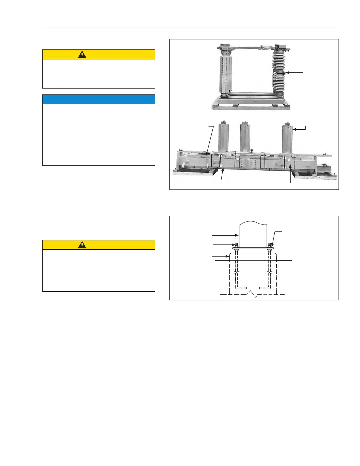
Figure 2. Typical shipment of Model 2020 Series 2000 Circuit-Switcher.
Operator is shipped on a separate skid.
Pole-unit
Interrupter
(inside container)
High-Speed base
Support arms
Mounting pedestal
Figure 3. Pedestal anchor-bolt mounting detail.
Two nuts and two
flat washers provide
leveling means
Pedestal
Anchor bolts
Concrete pad
 Loading...

