14 S&C Instruction Sheet 716-504
Installation
Installing the Operator
Step 7
Loosen the ½–13×1¼-inch galvanized steel cap
screws, at washers, and nuts used to attach the
bottom plates and lifting angles to the underside
of the high-speed base. Remove the plates and
place them and their hardware aside on a clean
surface. Discard the lifting angles. See Figure7.
Remove the ¾-inch stainless-steel pin and
cotter pin from the inter-phase drive lever
enclosed in the high-speed base. See Figure8.
Retain for re-use in Step 18.
CAUTION
Do not attempt to right the operator by
slinging to the skid. The skid is not designed
to carry the weight of the switch operator.
Damage to the operator or minor personal
injury may result.
Step 8
Wrap a lifting sling around the stored-energy
housing of the operator, as shown in Figure9.
Carefully raise the operator to the upright
position so it rests on its skid.
CAUTION
Do not remove the lifting sling around the
stored-energy housing. The operator is top-
heavy and must be adequately supported
until it is attached to the circuit-switcher.
Damage to the operator or minor personal
injury may result.
Step 9
Remove the skid and bracing that runs the
length of the operator, stored-energy housing,
and operator support tube. See Figure9. Also
remove the protective packing on top of the
operator support tube as well as the protective
covers on the operator enclosure louvers. See
Figure9 and Figure 10 on page 15.
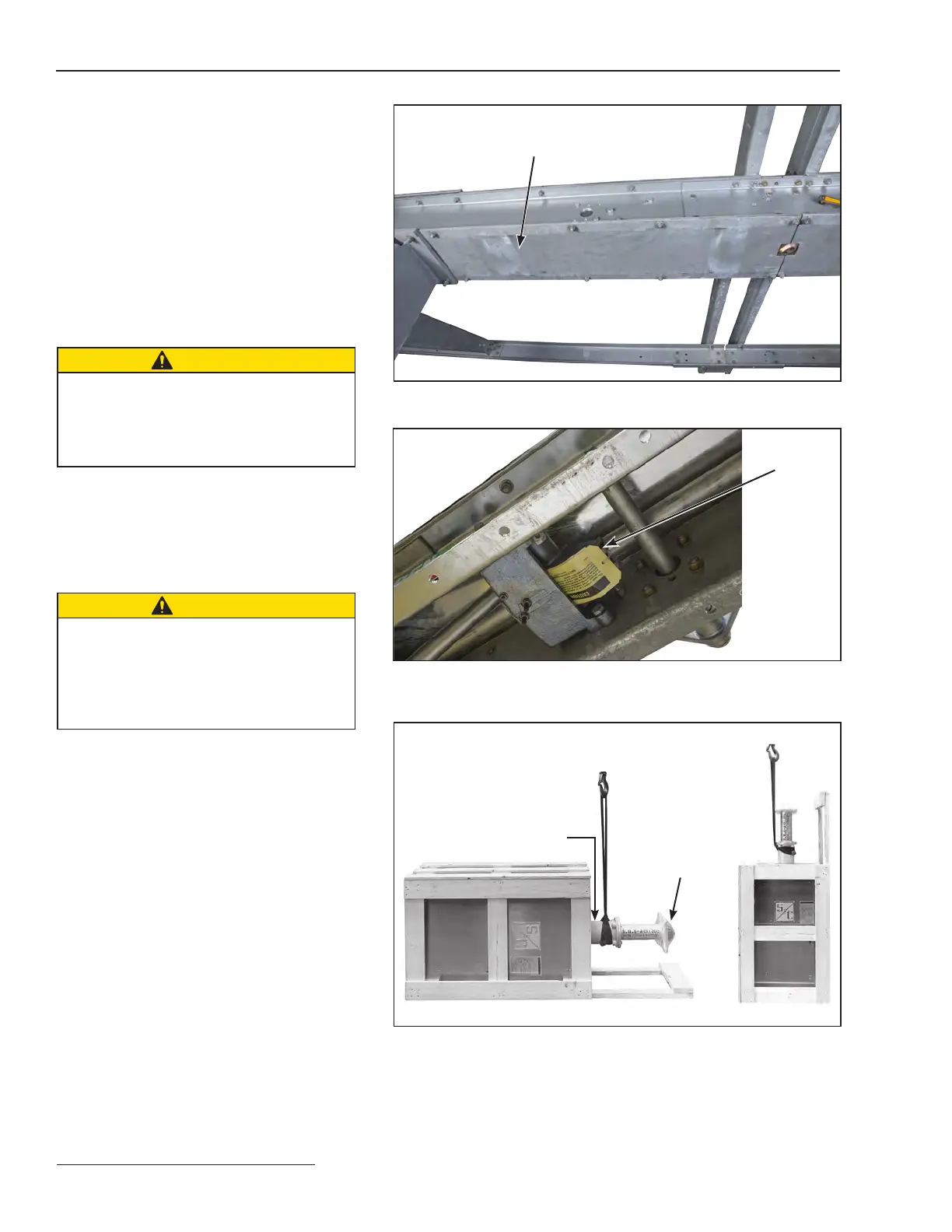
Figure 7. Remove bottom plates from high-speed base.
Figure 8. Remove the ¾-inch stainless-steel pin and cotter pin from the
interphase drive lever inside the high-speed base.
Figure 9. (Right and Left) Typical shipment of Series 2000 Operator. Wrap
lifting slings around stored-energy housing to raise the operator to the
upright position.
Stored-energy housing
Bottom plate
Packing
Pin and
cotter pin
 Loading...

