S&C Instruction Sheet 716-504 33
Installation
Step 36
When the circuit-switcher is ready to be placed
in service, the motor and closing circuit fuses
can—at the user’s option—be replaced with the
slugs furnished. This practice is recommended
for increased reliability because low-voltage
fuses can be damaged by the repeated inrush
current experienced during normal opening and
closing operations and can "sneak out," leaving
the circuit-switcher inoperable.
NOTICE
Before replacing these fuses with slugs,
make certain that the control-source battery
is adequately protected to prevent discharge
using fuses or circuit breakers located at the
battery bus.
Step 37
Please complete and mail the circuit-switcher
registration card. The information requested on
this card is vital to ensure prompt notication in
the event eld modications are needed.
Adjusting Auxiliary-Switch Contacts
Two individually adjustable auxiliary-switch
contacts are furnished in the operator. These
contacts follow the position of the disconnect-
blade power train and operator when the power
train is coupled and the position of the operator
when the power train is decoupled.
Step 38
Each auxiliary-switch contact is operated by
a cam-actuated roller. A contact is closed if its
roller is disengaged from a cam and, conversely,
a contact is open if its roller is engaged with a
cam. The cams are individually adjustable in
4.5-degree increments.
To adjust the contacts:
(a) Push the cam toward its adjacent spring
until the cam is separated from the teeth
of the inner gear. See Figure 40.
(b) Rotate the cam to advance or delay
engagement with its roller.
(c) Release the cam, making sure the teeth
are engaged with the inner gear.
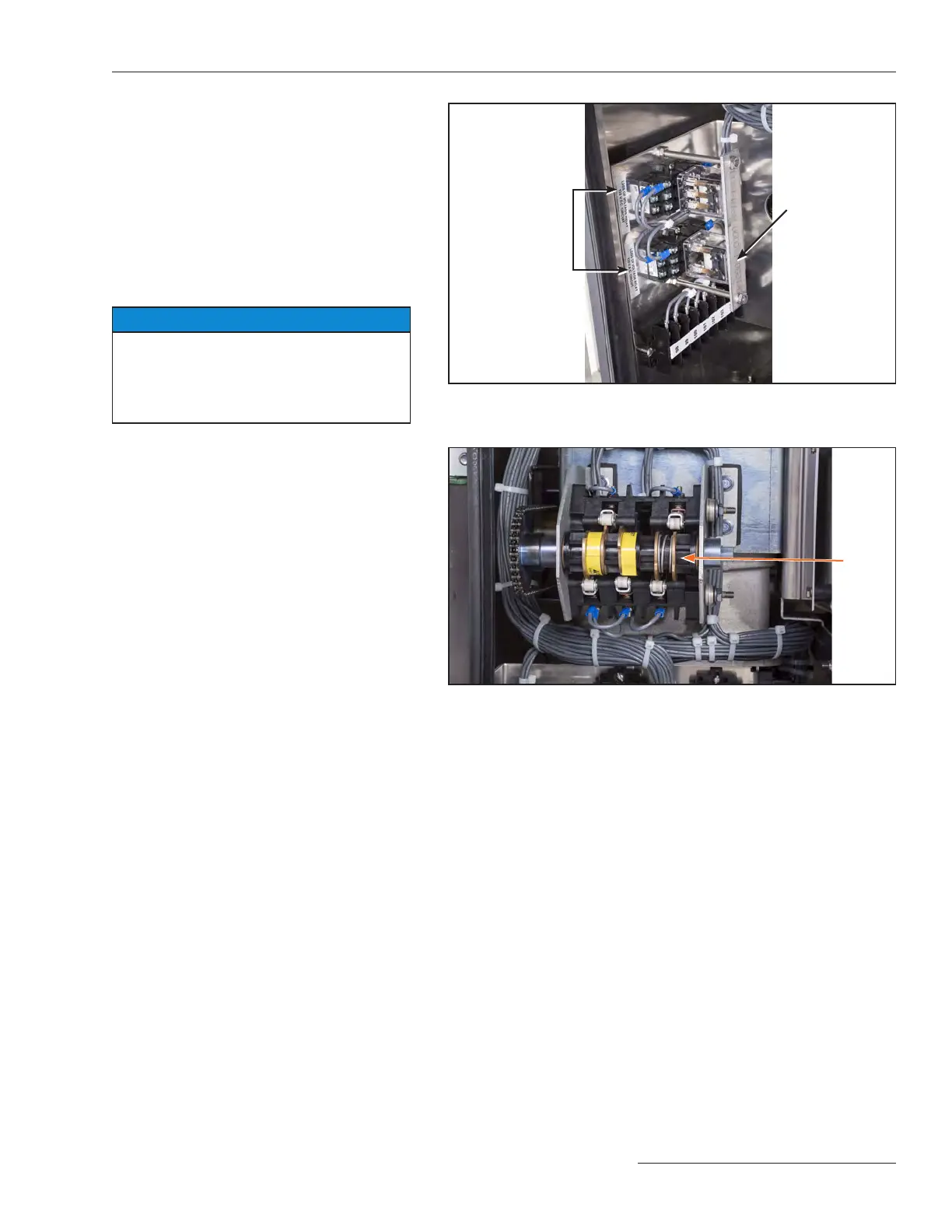
Figure 39. Check that all optional “ice cube” style relays are fully seated
and that the retaining plate is in place.
Figure 40. Adjust the cams on the auxiliary switch.
Cam
Optional relays
Relay holder
 Loading...

