S&C Instruction Sheet 716-504 5
Safety Information
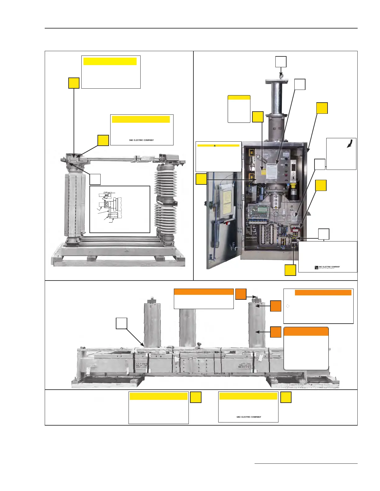
Location of Safety and Instruction Labels and Tags
ÇCAUTION
Transition box contains a stop bracket and spacer
which must be removed during installation, in the
manner described in the S&C instruction sheet
furnished with this Circuit-Switcher. Failure to do so
can result in damage to the Circuit-Switcher when
operated.
S&C ELECTRIC COMPANY
G-5807 Rev. 003 CHICAGO, ILLINOIS 60626 MADE IN U.S.A.
CHICAGO, ILLINOIS
G-5951 Rev. 001 MADE IN U.S.A.
Ç CAUTION
REMOVE the interrupter operating-rod holding bracket, stop bracket and
spacer during installation.
These packing parts are used to secure the switch during shipping and
installation. Instructions for when to remove the packing are in the Series
2000 Circuit-Switcher installation instruction sheet.
Failure to remove the packing may result in equipment damage or injury.
D
(Not visible)
Back
Base of Interrupter
N
Ç WARNING
MADE IN U.S.A.
S&C ELECTRIC COMPANY
CHICAGO, ILLINOIS 60626
G-5699 Rev.003
DO NOT remove steel outer wrapper until installation
is complete.
Interrupter contains gas under pressure.
Injury or damage to equipment may result.
Q
Ç WARNING
DO NOT remove steel outer
wrapper until installation is
complete.
Interrupter contains gas under
pressure.
Injury or damage to equipment
may result.
G-5993 REV. 003 MADE IN U.S.A.
S&C ELECTRIC COMPANY
CHICAGO, ILLINOIS
R
ÇCAUTION
CONNECT the interphase drive lever to the operator uni-ball coupling with
the attached pin.
An adjustable locking rod is provided to assist in making the connection. The
locking rod must be removed after installation. The locking rod is used to
secure the switch during shipping and installation. Instructions for when to
remove the locking rod and how to connect the interphase drive are in the
Series 2000 Circuit-Switcher installation instruction sheet.
Failure to properly install the drive lever may result in equipment damage or
injury.
MADE IN U.S.A.G-5949 Rev. 001
S&C ELECTRIC COMPANY
CHICAGO, ILLINOIS 60626
S
CHICAGO, ILLINOIS
G-5950 Rev. 001 MADE IN U.S.A.
Ç CAUTION
CONNECT the insulated operating rod to the interphase drive in the cross
base using the attached pin.
Instructions for making the connection are in the Series 2000 Circuit-Switcher
installation instruction sheet.
Failure to connect interphase drive pin may result in equipment damage or
injury.
T
G-5713 REV. 001 S&C ELECTRIC COMPANY MADE IN U.S.A.
DO NOT LIFT SWITCH WITH THIS BRACKET.
BRACKET MAY ONLY BE USED TO LIFT INTERRUPTER
AND SUPPORT COLUMN.
DAMAGE TO EQUIPMENT OR PERSONAL INJURY MAY
RESULT.
P
A
B
G-5685R1 MADE IN U.S.A.
S&C ELECTRIC COMPANY
CHICAGO, ILLINOIS
Connecting-Pin Installation
Pin
Retaining
Clip
Link
Stop
Bracket
5/16 Screw
Link, connecting
pin, and pin retain-
ing clip must be posi-
tioned as shown.
IMPORTANT:
After connecting
link to coupling,
remove 5/16 screw,
stop bracket, and
spacer before operat-
ing Circuit-Switcher.
Spacer
Connecting Pin
C
F
E
H
K
When the Circuit-Switcher is ready to be placed in service, the motor-and-closing
circuit fuses can—at the user’s option—be replaced with the enclosed slugs. This
practice is recommended for increased reliability because low-voltage fuses can be
damaged by the repeated inrush current experienced during normal Circuit-
Switcher opening and closing operations and can thus sneak out, leaving the
Circuit-Switcher inoperable.
Before replacing these fuses with slugs, make certain that the control-source
battery is adequately protected to prevent discharge, using fuses or circuit breakers
located at the battery bus.
G-5939 REV. 001 CHICAGO, ILLINOIS MADE IN U.S.A.
INSTRUCTION FOR FUSE SLUGS
For Series 2000 Operators
J
IMPORTANT
Access shutter is inter-
locked with interrupters.
Trip interrupters, open
access shutter, and engage
operating shaft. Then rotate
shaft, clockwise only, to
open integral disconnect.
G-5675R1
G
CAUTION
Do not apply control voltage to this device or manually operate it until installation has been
completed and the following items have been checked. Damage to the Circuit-Switcher can result!
1. At each transition box:
• The operating-rod holding bracket, stop
bracket, and spacer have been removed
from the interrupter
• The interrupter coupling has been
connected to its insulated operating
rod link.
2. In the cross base:
• Each insulated operating rod has been
con nected to the interphase drive
• The interphase drive lever has been
connected to the operator uni-ball coupling
• The adjustable locking rod attached to the
inter phase drive lever has been removed.
3. All other pinned connections have been
made and all bolted connections have
been securely tightened.
4. At the operator:
• Correct polarity has been observed on
dc-control-voltage models.
Refer to the S&C instruction sheet furnished with this Circuit-Switcher.
G-5947
S&C Series 2000 Circuit-Switcher Models 2020 & 2025
PRESSURE SENSITIVE STRIP REVERSE SIDE ONLY
PRESSURE SENSITIVE STRIP REVERSE SIDE ONLY
L
Ç
CAUTION
Do not attempt to close
Circuit-Switcher using
manual trip lever.
Damage to mechanism
may result.
S&C ELECTRIC COMPANY
CHICAGO ILLINOIS
G-6222 Rev. 001
M
 Loading...

