S&C Instruction Sheet 716-504 15
Installation
Step 10
Reposition the lifting sling around the front of
the stored-energy housing and wrap another
lifting sling around the back of the stored-
energy housing, as shown in Figure 10. Face the
operator door the same direction as the switch
position indicator on the high-speed base. Hoist
the operator into place.
NOTICE
DO NOT damage the uni-ball coupling on
the operator connecting link during hoisting
and attachment of the operator. The uni-
ball coupling cannot be replaced in the
field. Damage will necessitate returning the
operator for replacement.
Attach the operator support tube mounting
plate to the underside of the high-speed base
using four ½–13×1¾-inch hex-head galvanized
steel cap screws, flat washers, and self-locking
hex nuts. Lubricate the bolts to facilitate tight-
ening. Tighten all four screws securely.
Step 11
Attach the operator support angle to the
appropriate mounting pedestal using two
⅝–11×14-inch hex-head galvanized steel cap
screws, four at washers, and two self-locking
hex nuts. Refer to the catalog drawing for exact
placement. See Figure 10.
Attach the operator support plate to the
angle on the operator, and the angle on the
mounting pedestal using four ½–13×1½-inch
hex-head galvanized steel cap screws, flat wash-
ers, and self-locking hex nuts furnished. Lubri-
cate the bolts to facilitate tightening. Securely
tighten the screws. On circuit-switchers with
two mounting pedestals, insert the hole plugs
furnished into all unused holes in the pedestals.
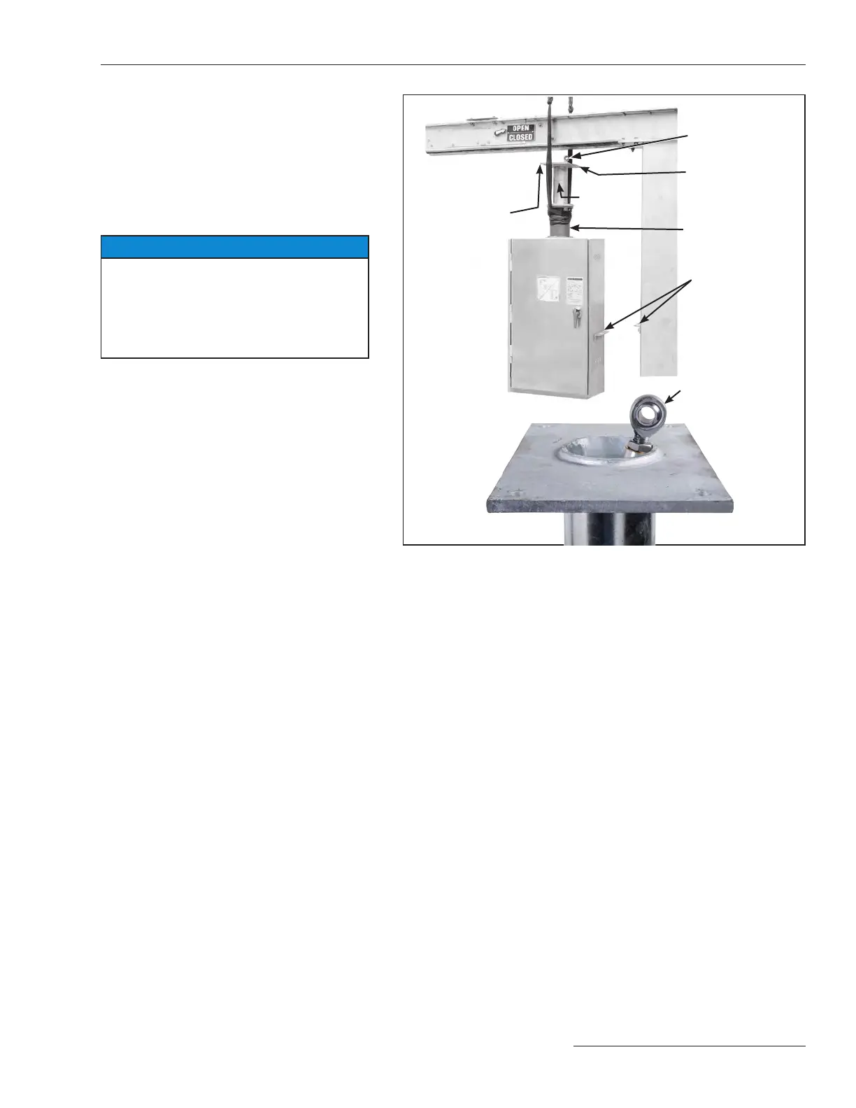
Figure 10. Hoist operator into position below the high-speed base using
a lifting crane.
Uni-ball coupling
Operator
support
tube
Stored-energy
housing
Uni-ball coupling
Operator support
tube mounting
plate
Holes for
½ –132¾-inch
hex-
head galvanized
steel cap screws,
flat washers, and
self-locking nuts
Operator
support
angles
 Loading...

