S&C Instruction Sheet 716-504 19
Installation
Step 15
Attach the interrupter to its insulating support
column as follows:
(a) Remove and discard the shipping cover
on top of the transition box. See Figure 13
on page 18, inset.
(b) Thoroughly wire-brush the top of the
transition box and mating surface on the
interrupter, and immediately apply a
liberal coating of Burndy Penetrox
®
A
(available from Burndy Corporation)
or an equivalent aluminum-connector
compound to the brushed surfaces.
(c) Remove the four 5⁄16–18×¾-inch hex-
head stainless steel cap screws used to
attach the access cover to the side of the
transition box. Remove the cover and
place it and the hardware on a clean
surface. See Figure 13 on page 18. Also
remove the cloth bag containing the
hardware that will be used to connect the
interrupter coupling to the operating rod
link in Step15(g).
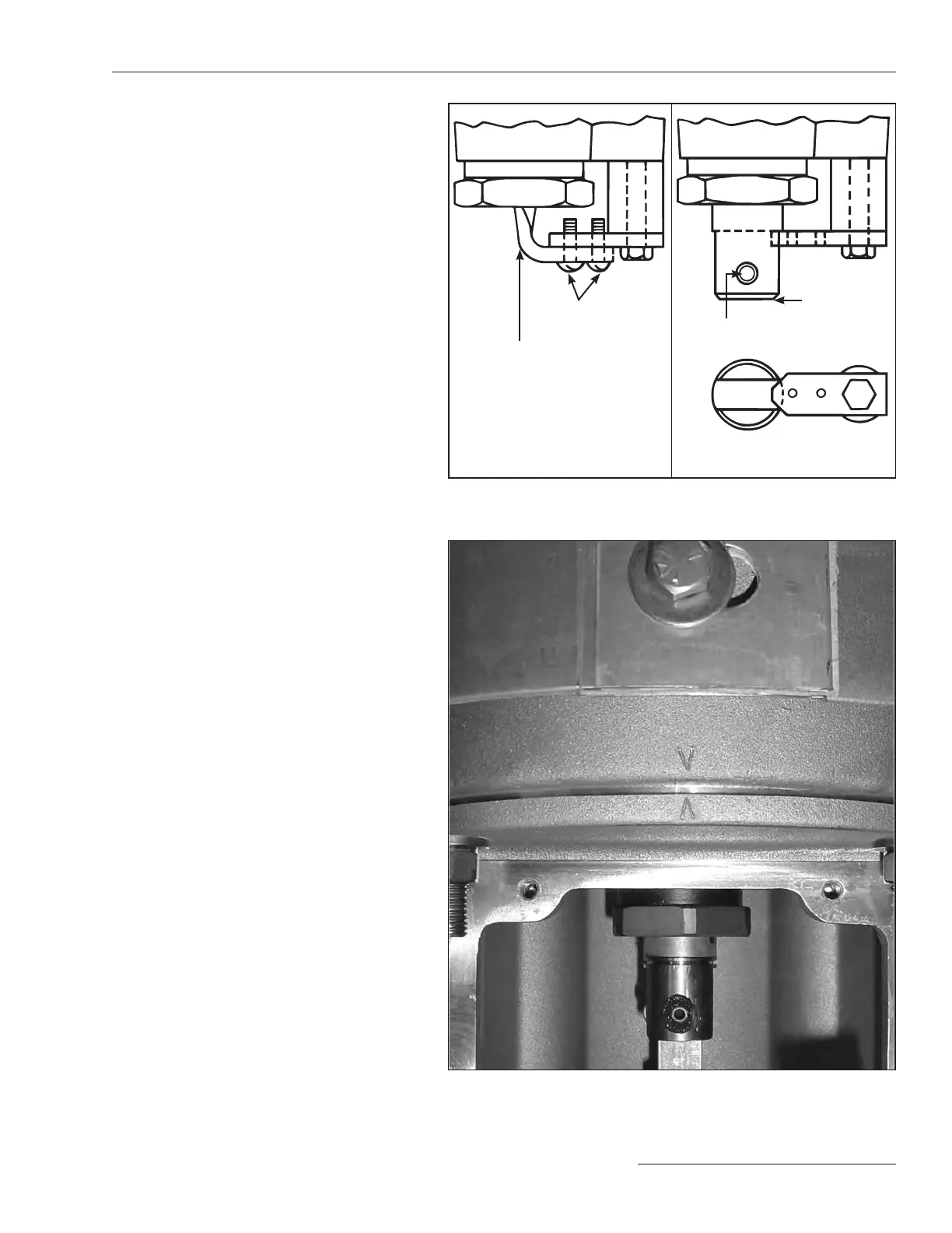
(d) Make certain the positioning mark
stamped on the bottom of the interrupter
is aligned with the position mark stamped
on the top of the transition box. See
Figure15.
(e) Lower the interrupter onto the transition
box. One of the ½–13-inch stainless-steel
studs on the interrupter is longer than
the other three to aid in aligning the
interrupter with the transition box.
(f) Reattach a ½-inch Belleville washer and
a ½–12-inch stainless-steel hex nut,
retained from Step13, to each of the four
studs. Lubricate the nuts to facilitate
tightening. Tighten each nut securely.
(g) Attach the insulated operating rod end
links to the interphase drive linkage lever
in the high-speed base using the ½-inch
silicon-bronze pin and cotter pin retained
from Step12(d). See Figure16 on page
20. The insulated operating rod may be
moved up or down, as required, to make
the connection.
(h) Insert the connecting pin retained from
Step 14(c) into the coupling and
operating rod link. See Figure 17 on
page 20. It will be necessary to loosen
the 5⁄16–18×2¼-inch hex-head stainless-
steel screw indicated in Figure 17 on
page 20 and withdraw it approximately
⅛-inch so the connecting pin can be
inserted. Do not remove the stop
bracket screw at this time.
Figure 15. Align the positioning mark on the interrupter with the mark
on the transition box.
Figure 14. Prepare the interrupter for attachment to the insulating support
column.
Operating-rod holding
bracket (marked with a
black/yellow striped label)
Connecting pin
#10–32 screws
Operating rod in shipping
position
Coupling
Operating rod in fully open
position
 Loading...

