S&C Instruction Sheet 716-504 23
Installation
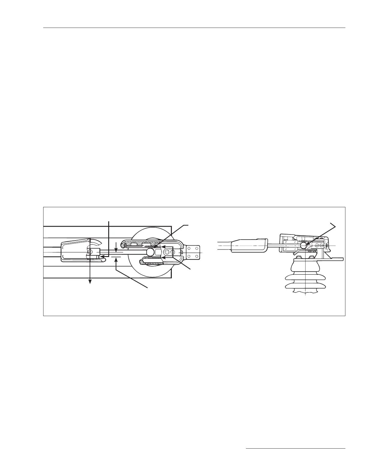
Step 21
Close the disconnect blade on each pole-unit.
The disconnect-blade corona-ball contact
must be centered on its jaw-contact ngers,
and the blade must touch its stop as indicated
in Figure 24. Connect the factory-adjusted
interphase pipe assembly to the center pole-
unit insulating support column drive lever
using the ½-inch stainless steel pin, two
galvanized steel spacers, and two stainless
steel “X” washers furnished. See Figure26 on
page 24. Attach the interphase pipe assembly to
the two outboard pole-unit insulating support
column drive levers.
In the event that the interphase pipe
assembly cannot be connected to an outboard
pole-unit insulating support column drive
lever, loosen the appropriate locknut at the
adjustable coupling and rotate the affected
interphase pipe section so the connection
can be made, then tighten the locknut. See
Figure27 on page 25.
Figure 24. Check the engagement of disconnect-blade corona-ball contact with the jaw-contact fingers.
Corona-ball contact
Jaw-contact fingers
Blade stop
See Steps 25 and 26
40-pound pull-out force
Maximum allowable deflection: ½ inch
Top View Side View
Center-line of corona-ball
contact and jaw-contact
assembly
 Loading...

