S&C Instruction Sheet 716-504 31
Installation
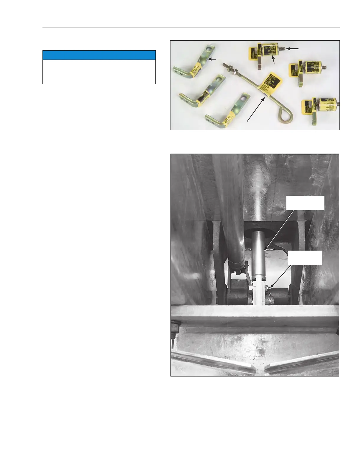
Figure 34. Check the transition box and high speed base for these
shipping parts.
Figure 35. Check that each insulated operating rod has been connected
to the interphase drive.
Step 31
Perform nal checkout as detailed below:
NOTICE
Check the following. Failure to do so can
result in damage to the circuit-switcher
when operated.
(a) At each transition box check that:
• The operating rod holding bracket, stop
bracket, and spacer have been removed
from the interrupter. See Figure 34.
• The interrupter coupling has been con-
nected to its insulated operating rod
link. See Figure 17 on page 20.
• When the optional remote gas-density
monitor is present (Catalog Number
Sufx “-R”) make sure connections are
made according to Instruction Sheet
716-530.
(b) At each interrupter make sure:
• That both interrupter container halves
and all associated packing and hardware
have been removed
(c) In the high-speed base:
• Each insulated operating rod is con-
nected to the interphase drive. See
Figure 35.
• The interphase drive lever has been
connected to the operator uni-ball cou-
pling. See Figure 36 on page 32.
• The adjustable locking rod attached
to the interphase drive lever has been
removed. See Figures 34 and Figure 36
on page 32.
(d) In the switch operator make sure:
• Correct polarity has been observed
on dc-control-voltage models.
See Figure37 on page 32.
• Check the open and close motor
contactors and surge suppressor to
ensure all electrical connections are
secure, and that all contactors and
surge suppressors are fully-seated in
their mounts. See Figure 38 on page 32.
• That any optional “ice cube” style
relays (used for Catalog Option “-P”
and “-T2”) are fully seated. See Figure
38 on page 32.
(e) All other pinned connections have been
made and all bolted connections have
been securely tightened.
Adjustable locking rod
Stop bracket
Operating
rod holding
bracket
Insulated
operating rod
Interphase
drive
Spacer