Installation
S&C Instruction Sheet 716-500 11
Components
and hardware
High-speed base
Interrupter
Insulating
support column
Shipping channelShipping support
Circuit-Switcher rated 161 kV though 230 kV
Figure 2b. Typical shipment of Model 2030 Series 2000 Circuit-
Switcher. Operator is shipped on a separate skid. (161-230 kV)
Pedestal
Two nuts and two flat washers
provide leveling means
Anchor bolts
Concrete pad
Figure 3. Pedestal anchor-bolt mounting detail.
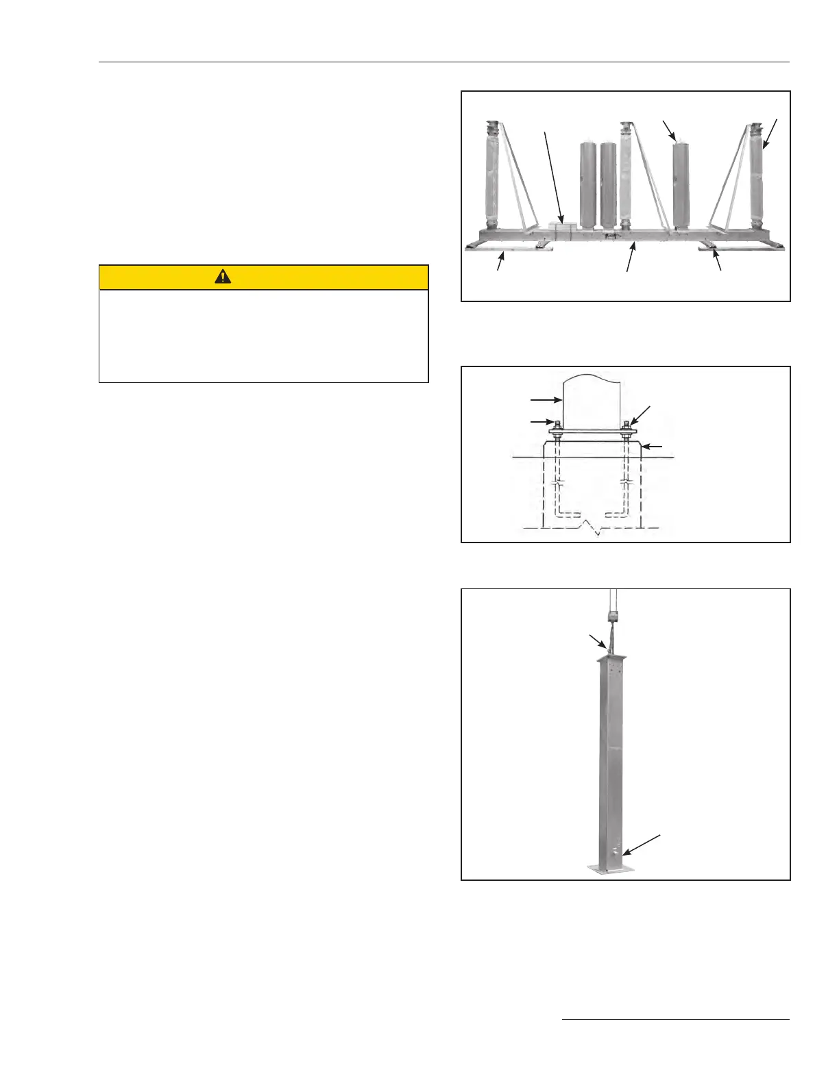
Eye bolts
Grounding pad
Figure 4. Lift the pedestal into position.
STEP 1. For circuit-switchers rated 69 kV through 138 kV:
Cut the steel straps that bind the mounting pedestals
to the high-speed base and the straps that bind the
container of operating mechanism components
and hardware and the straps that bind the pole-
units using a steel strapping cutter. See Figure 2a
on page 10.
For circuit-switchers rated 161 kV and 230kV:
Cut the steel straps binding the container of mis-
cellaneous operating-mechanism components and
hardware. See Figure 2b.
CAUTION
The foundations and anchor bolts for S&C mounting
pedestals must be designed to meet the loading limits
specified in S&C Data Bulletin 716-61.
Failure to meet these loading limits can result in personal
injury and equipment damage.
Installing the Mounting Pedestals and
High-Speed Base
STEP 2. Install each pedestal as follows:
(a) Install the lower set of anchor bolt nuts and at
washers onto the pre-installed anchor bolts. Level
all anchor bolts to the same height, leaving space
below and above the bolt for leveling. See Figure 3.
(b) Install the temporary eyebolts into the holes
provided at the top of the mounting pedestal. Attach
the lifting slings to the eyebolts. See Figure 4.
(c) Lift the pedestal over the anchor bolts. Before low-
ering, make sure the grounding pad is positioned
properly for the installation. Refer to the accompa-
nying catalog drawing for details. See Figure 4.
(d) Lower the pedestal onto the anchor bolt nuts and
at washers. Loosely secure a at washer and nut to
each anchor bolt. See Figure 3. Remove lifting
slings and eyebolts.
(e) Adjust the lower set of anchor-bolt nuts to plumb
and level the pedestal. The upper set of anchor bolt
nuts should remain loosely attached. See Figure 3.
 Loading...

