Operation
28 S&C Instruction Sheet 716-500
To close the Circuit-Switcher, press the CLOSE pushbut-
ton or send a remote close signal to the switch operator. See
Figure 23 on page 22.
The motor-driven cam in the stored-energy mechanism
will immediately start retracting. The closing latch will
release, discharging the closing spring. This action closes the
interrupters. The switch position indicator on the high-speed
base will move to the Closed position. See Figure33. If the
position-indicating lamp option has been specified, the red
lamp will light.
The Circuit-Switcher may also be electrically operated
via remotely located control switches. No instructions are
included for remote control because control schemes vary
with the installation and specific application of the switch.
Manual Operation
To trip the interrupters, push the manual TRIP lever
counterclockwise as indicated by the TRIP lever label. See
Figure 23 on page 22. The opening latch in the stored-energy
mechanism will release, discharging the opening spring.
This action trips the interrupters and forces the opening
and closing pistons in the mechanism downward, as shown
by movement of the indicator to the Discharged window.
(See Figure 32 on page 27.) The switch-position indicator on
the high-speed base will move to the Open position. (See
Figure 33.) If the position-indicating lamp option has been
specied—and operator control voltage is available—the
green lamp will light.
If operator control voltage is available, the motor-driven
cam in the stored-energy mechanism will immediately start
rising, charging both the opening and closing springs. When
the opening spring latches, the indicator will again be visible
at the Charged window.
If operator control voltage is not available, the interrupt-
ers will open. The motor-driven cam in the stored-energy
mechanism will charge the opening and closing springs when
control power is restored to the operator.
Manual closing of the circuit-switcher cannot be per-
formed.
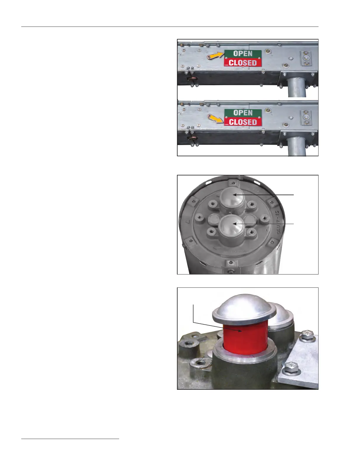
Understanding the Gas-Pressure Indicator
and Safety Relief Device
Series 2000 Circuit-Switchers have sealed interrupters
containing gas under pressure. Loss of gas pressure may
result in improper interrupting action. Low gas pressure is
signaled by a red target in the Gas-Pressure indicator at the
upper terminal end of the interrupter.
Figure 34 illustrates a Gas-Pressure indicator with
acceptable gas pressure.
Figure 35 illustrates a Gas-Pressure indicator with a red
target, signaling a loss in gas-pressure.
Figure 33. A switch-position indicator in the OPEN position.
The switch-position indicator in the CLOSED position.
Gas
pressure
indicator
Safety
relief
device
Figure 34. A normal gas-pressure indicator and relief device.
Red target
(semiphore)
Figure 35. A visible “red target” gas-pressure indicator.
 Loading...

