
T
Theodore HoustonJul 30, 2025
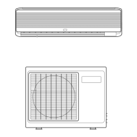
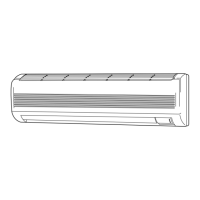
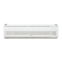
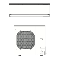
Why is my Sanyo Air Conditioner not cooling well?
- CChristina JordanJul 30, 2025
Several factors can cause poor cooling performance in your Sanyo Air Conditioner. Check the following: * Clean or replace a dirty or clogged air filter to improve airflow. * Reduce or eliminate heat sources in the room. * Ensure doors and windows are closed. * Remove any obstacles near the air intake or air discharge port to ensure good airflow. * Lower the thermostat setting.