-55-
Electrical Adjustments
● Circuit Adjustment
CAUTION: The each circuit has been made by the fine adjustment at factory. Do not attempt to adjust the follow-
ing adjustments except requiring the readjustments in servicing otherwise it may cause loss of perfor-
mance and product safety.
[Adjustment Condition]
● Input signal
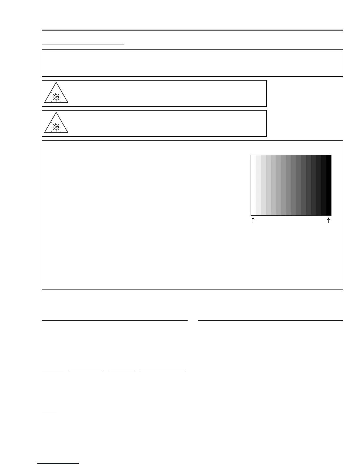
Computer signal .................... 0.7Vp-p/75Ω terminated, 16 steps gray
scale pattern, 1 line dot pattern, 100%
and 50% whole white pattern (720p for-
mat)
Component Video signal........ 0.7Vp-p/75Ω terminated, 16 steps gray
scale pattern (480i, 480p, 720p and
1080i format), 100% and 50% whole
white pattern (480p format)
Video signal .......................... 1.0Vp-p/75Ω terminated, 16 steps gray
scale pattern (NTSC composite video
signal)
● Image level selection................ “Powerful” mode unless otherwise noted.
Note:
* Please refer to “Service Adjustment Menu Operation” for entering to the
service mode and adjusting the service data.
16 steps gray scale pattern
Equipment Digital voltmeter
1. Enter the service mode.
2. Change data values of each test points to adjust the
fan minimum output voltage.
Item no. Fan Location Test Point Adjustment value
102 - 7 FN901 TPFAN1 3.5 ±0.05Vdc
102 - 8 FN902 TPFAN2 3.5 ±0.05Vdc
102 - 9 FN903 TPFAN3 3.5 ±0.05Vdc
102 - 10 FN904/5 TPFAN4 3.5 ±0.05Vdc
Note:
The location of each fan is refer to the parts list.
z Fan minimum voltage adjustment
Equipment NIL
After replacing or repairing the LAMP IRIS, this re-
adjustment is needed.
1. Enter the service mode.
2. Select group/item no. "105 - 14", and change data
value from “0” to “1”, then automatic iris adjustment
will be done.
3. After this adjustment, change this data value from
“1” to “0” for normal operation.
x Iris adjustment
WARNING : USE UV RADIATION EYE AND SKIN PROTECTION
DURING SERVICING
CAUTION: To prevent suffer of UV radiation, those adjustments
must be completed within 25 minutes.
 Loading...