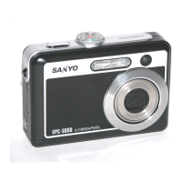
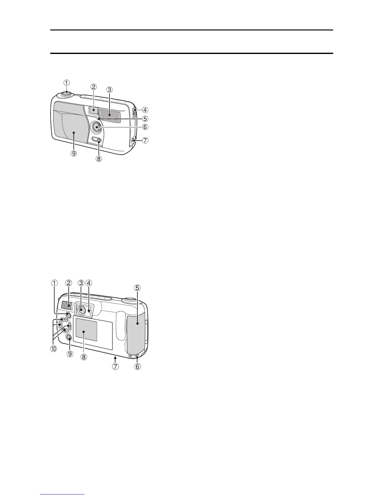
PART NAMES
Front
1
Shutter release button
2
Viewfinder
3
Flash
4
USB terminal
For connecting to a computer with the
supplied USB interface cable.
5 Self-timer indicator
6
Lens
7
DC IN terminal (for external DC power
input)
For connecting the VAR-G5EX/E/U AC
Adapter (sold separately).
8 Macro switch
9
Lens cover
Rear
1 [MODE] button
2
Main switch
3
Viewfinder
4 Standby indicator
5 Card slot cover
6 Strap holder
7
Battery compartment cover
8 LCD monitor
9 [SET] button
F Arrow button
œ During use, the area around the LCD monitor
may become warm. This is normal and does
not indicate a malfunction.
œ You may see some black and white dots in
the LCD monitor. This is normal and does not
indicate a malfunction.
English
14
 Loading...