13.
FUSE
Fuses are installed
on
the
wiring inside
the
instrument panel, including
1 0-A fuses for
the
pilots of
the
water temperature warning lamp,
battery ·charge warning lamp and oil pressure warning lamp incorporat-
ed
in
the
tractor meter,
and
two 1 0-A fuses (in a fuse holder) for
the
light switch. If any fuse
is
burned
out,
check for
the
cause before
replacement.
Light
switch
Flood
lamp
Yellow
Water temperature warning
light
Red
Battery charge warning lamp
White
Oil pressure warning lamp
Yellow
14. BRAKE ADJUSTMENT
Red Blue
Starter switch
(8)
Red
Yellow
Starter switch
(1G)
Fig.
42
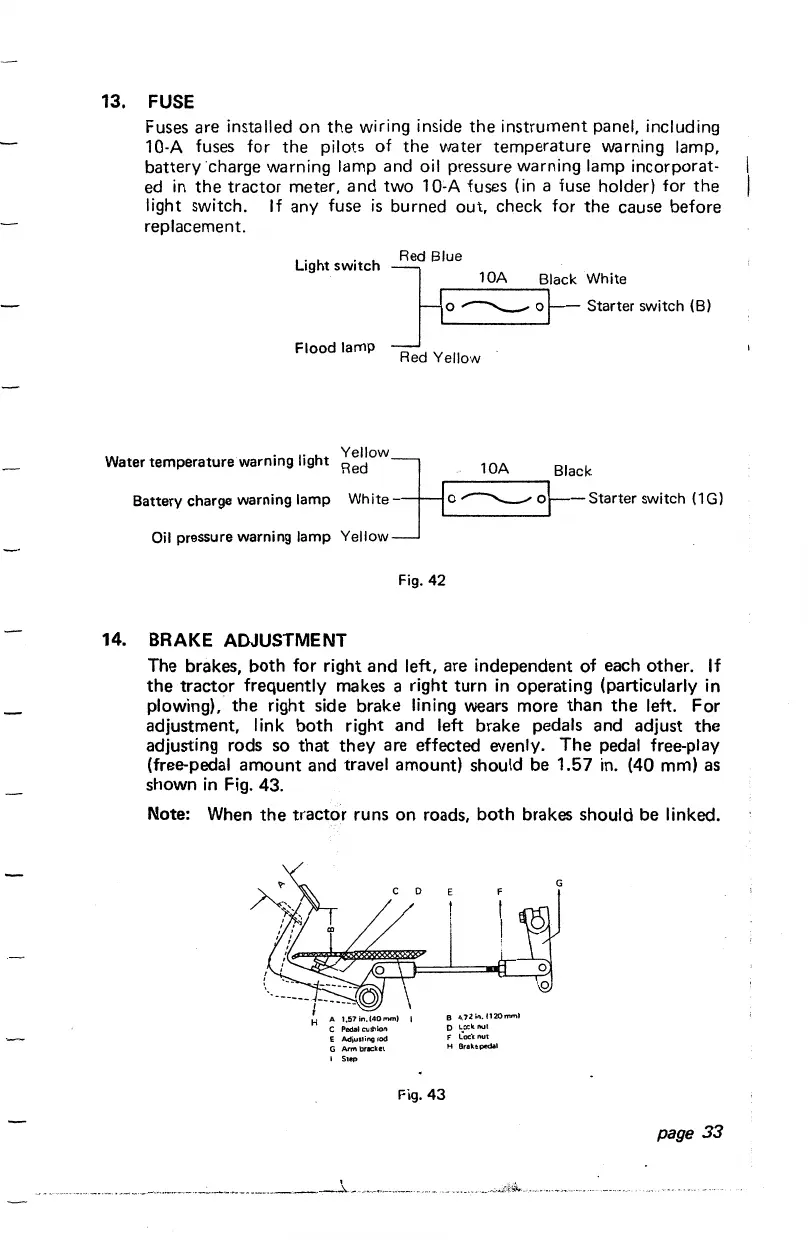
The brakes,
both
for right
and
left, are independent of each other. If
the
tractor
frequently makes a right
turn
in operating (particularly in
plowing),
the
right side brake lining wears more
than
the
left.
For
adjustment, link
both
right
and
left brake pedals
and
adjust
the
adjusting rods so
that
they
are effected evenly.
The
pedal free-play
(free-pedal
amount
and
travel amount) should be
1.57
in.
(40 mm) as
shown
in
Fig. 43.
Note: When
the
tractor
runs
on
roads,
both
brakes should
be
linked.
E
Adiu51i!'IG
rod
G
Arrnbr~elcet
I
Slep
.
···-···-··--··-······-·--·-·--·--------------->--
Fig.
43
D L:x:krou!
F
L~ock
nut
H Brake pedal
page
33
 Loading...