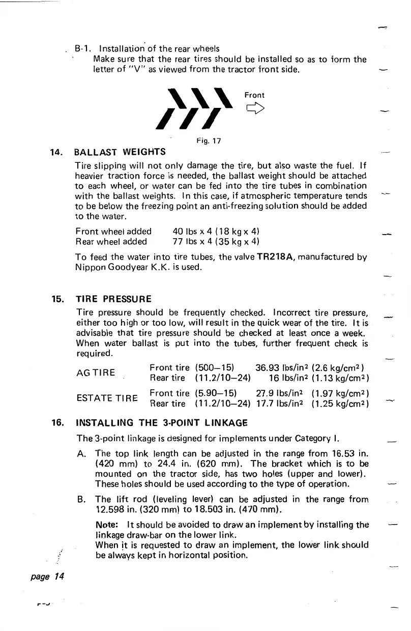
B-1.
Installation of
the
rear wheels
Make sure
that
the
rear
tirr:ls
should be installed so
as
to
form
the
letter
of
"V"
as
viewed from
the
tractor
front
side.
Front
Fig.
17
14. BALLAST WEIGHTS
Tire slipping will
not
only damage
the
tire,
but
also waste the fuel.
If
heavier traction force
is
needed,
the
ballast weight should be attached
to
each wheel, or water can be fed into the tire tubes
in
combination
with
the
ballast weights.
In
this case,
if
atmospheric temperature tends
to
be below
the
freezing point an anti-freezing solution should be added
to
the
water.
Front wheel added
Rear wheel added
40
lbs
X 4 (
18
kg
X
4)
77 lbs X 4 (35 kg X
4)
To
feed
the
water into tire tubes,
the
valve TR218A, manufactured by
Nippon Goodyear K.K.
is
used.
15.
TIRE
PRESSURE
Tire pressure should be frequently checked. Incorrect tire pressure,
either
too
high or
too
low, will result in
the
quick wear of
the
tire.
It
is
advisable
that
tire pressure should
be
checked
at
least once a week.
When water ballast
is
put
into
the
tubes, further frequent check
is
required.
AG
TIRE
ESTATE TIRE
Front
tire
(500-15)
Rear tire ( 11.2/1
0-24)
Front
tire
(5.90-15)
Rear tire
(11.2/10-24)
36.93
lbs/in2 (2.6 kg/cm2)
16 lbs/in2 ( 1.13 kg/cm2)
27.91bs/in2 (1.97 kg/cm2)
17.7 lbs/in2 (1.25 kg/cm2)
16. INSTALLING THE 3-POINT LINKAGE
page
14
The
3-point linkage
is
designed for implements under Category
I.
A.
The
top
link length can be adjusted in
the
range from 16.53 in.
(420 mm)
to
24.4 in. (620 mm).
The
bracket which
is
to
be
mounted on
the
tractor side, has two holes (upper and lower).
These holes should be used according
to
the
type
of operation.
B.
The
lift rod (leveling lever) can be adjusted in
the
range from
12.598 in. (320 mm)
to
18.503 in. (470 mm).
Note: It should be avoided
to
draw
an
implement
by
installing
the
linkage draw-bar on
the
lower link.
When it
is
requested
to
draw
an
implement,
the
lower link should
be always
kept
in horizontal position.
 Loading...