www.scheppach.com / service@scheppach.com / +(49)-08223-4002-99 / +(49)-08223-4002-58
30
|
GB
8.2.1 Connection to an external dust extractor
• Connect the vacuum hose with the dust extraction
spout.
• The industrial vacuum cleaner must be suitable for
the material being worked.
• -
tal to health or carcinogenic, use a special vacuum
cleaner.
8.3 Precision adjustment of the stop for crosscut
90° (g. 1/2/5/6)
Tools required:
-
- Open-ended spanner SW13 (not included in the
• No stop angle included.
• Lower the machine head (4) and secure it using the
locking bolt (23).
• Loosen the set screw (22).
• Position the angle stop (A) between the saw blade
• Loosen the lock nut (26a).
• Adjust the adjusting screw (26) until the angle be-
• Tighten the lock nut (26a) again.
• -
Phillips screwdriver, set to position 0° on the angle
scale (18) and re-tighten the retaining screw.
8.4 Precision adjustment of the stop for mitre cut
45° (g. 1/2/5/9/10)
Tools required:
-
- Open-ended spanner SW13 (not included in the
• No stop angle included.
• Lower the machine head (4) and secure it using the
locking bolt (23).
•
Attention!
For bevel cuts (inclined saw head), the moveable
(Left side).
• Open the set screw (16b) for the moveable stop rail
(16a) and push the moveable stop rail (16a) out-
wards.
• The moveable stop rails (16a) must be locked so
that the distance between the stop rails (16a) and
the saw blade (6) is at least 8 mm.
• -
ner position. (Right side).
• Before making a cut, check that the stop rail (16a)
and the saw blade (6) cannot collide.
• Loosen the set screw (22) and use the handle (1) to
angle the machine head (4) 45° to the left.
•
identical to the mains data.
7.1 Checking the moving saw blade guard safety
device (5)
The saw blade guard protects against accidental con-
Check function
To do so, fold the saw downwards:
• The saw blade guard must provide free access to
the saw blade without touching other parts.
• When folding the saw upwards into the starting
position, the saw blade guard must cover the saw
8. Attachment
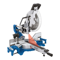
8.1 Attaching the crosscut, drag and mitre saw
(g. 1/2/4)
•
• -
sired angle measurement on the scale (13) and use
the handle (11) to secure it.
•
time, pulling out and turning the locking pin (23)
from the engine mount.
• Turn the locking bolt (23) 90 degrees to secure it in
the unlocked position.
• Swing the machine head (4) up.
• It is possible to secure the clamping devices (7) to
clamping devices (7) in the holes on the rear side
of the stop rail (16) and secure it with the star grip
screws (7a). For 0°- 45° mitre cuts, the clamping
• It is possible to tilt the machine head (4) a max. 45°
•
and used during work. Set the desired table size
screw (9) again.
8.2 Sawdust bag (g. 1/22)
The saw is equipped with a debris bag (17) for saw-
dust and chips.
Squeeze the wings of the metal ring on the dust bag
(17) together and slide it over the discharge port near
the engine.
zipper at the bottom.
 Loading...