8 • Schlage • AD-300 user guide
Lock address setup
Manually set the RS485 address
L The lock MUST NOT be connected to RS485 communication during this
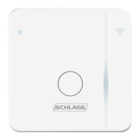
procedure.
1. Make sure that 12 or 24 VDC power is connected properly, and RS485 is not connected.
L The Schlage button will blink red to indicate no communication with the access
control panel.
2. Open the door.
3. Create a request-to-exit condition by holding down the inside lever or crash bar.
Continue to hold the inside lever or crash bar through step 5.
L If using a crash bar, Request to Exit (RTX) must be installed. If RTX is not
installed, temporarily short the RTX input on the lock main PCB during this
procedure.
4. Press and release the Schlage button on the lock. Wait for the Schlage button to ash
green.
The lock address is now set to zero (0).
5. Repeat step 4 until the number of times you have pressed the Schlage button
corresponds with the desired RS485 address.
L Two (2) total presses sets the address to one, three (3) total presses sets the
address to two, etc.
L Manual RS485 addresses may be assigned up to address “15” (16 total presses).
1
To assign addresses 16 - 255, use the SUS (lock properties, edit menu). For
further information, refer to the SUS user guide.
6. Release the inside lever or crash bar. The Schlage button will blink green, and the
beeper will beep to indicate conrmation.
L The number of green blinks and beeps indicates the RS485 address.
7. After the conrmation blinks and beeps are completed, the Schlage button will again
blink red to indicate no communication with the access control panel.
Set the RS485 address with Schlage utility software (SUS)
The RS485 address may be set using the SUS. Please refer to the Schlage utility software
user guide for details.
1 Check your ACP to determine how the address assignments run. Most access control systems run 1 - 16,
however some systems run 0 - 15 (true RS485).
 Loading...


