9 • Schlage • AD-300 user guide
Connect to an access control panel
• The two data wires from the panel (Data-A(-) and Data-B(+)) must be a shielded
twisted pair.
• In case of power outage, the lock will enter the congured power failure mode. See
Power failure on page 13 for more information.
• The AD-300/AD-302 may be connected to external power using a UL294 listed Power
Supply for UL installations, and a power supply that complies with CAN/UL-S318 or
CAN/ULC-S319 for cUL installations. The power supply must be capable of sourcing at
least 250 mA @ 12 or 24 VDC (Schlage PS902, PS904, PS906).
• For compliance with UL 294, product must be used with a UL 294 Listed access control
panel or unit. For compliance with CAN/ULC -S319, product must be used with a CAN/
ULC -S319 Listed access control panel or unit.
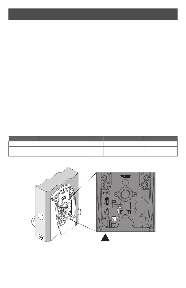
• The power supply may be connected to either: a) Auxiliary Power Inputs on the main
board or, b) VIN (PWR) and GND connectors on the RS485 communication board.
L The EIA RS485 Specication labels the data wires as “A” and “B” but many
RS485 products label their wires “+” and “-.” Some products associate the “+”
signal with “A”, some with “B”. The bottom line is that the “+” should always be
connected to the “+” and the “-” to the “-” , however it is designated. Reversing
the polarity will not damage either RS485 device, it will only fail to communicate.
Attempt to connect “+” to “+” and “-” to “-” . If it does not work, switch them.
WARNING: DO NOT attach power to A/B data terminals!
Cable/wire specications
Application Part number AWG Description Max run length
Dc power input Belden 8760 or equivalent 18 2 Conductor 1000 feet
RS485
Belden 9841 or 9842 or
equivalent
24
3 Conductor
shielded
4000 feet
1
1 RS485 has 4,000 foot (1,219 meter) maximum run length. Consult the ACP supplier for maximum run directly to
the ACP.
–
+
!
Polarity Required
 Loading...