21F-PD250 / 21F-PT220 / 21F-PA18 / 21F-PA18(B)
3 – 14
[2] ADJUSTMENT
ADJUSTMENT PRECAUTION: Makesure TV Set is in “Normal Condition” before switch to Service Mode for Adjustment.
1. PIF ADJUSTMENT
No.
Adjustment point
Adjustment procedure/conditions Waveform and others
Tuner IFT
( PRESET )
1 1. Get the tuner ready to receive the CH. E - 9
signal,but with no signal input.
Adjust the PLL data.
2. Connect the sweep generator's output cable to
the tuner antenna. ( RF SWEEP )
3. Adjust the sweep generator's to 80dBµV.
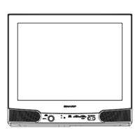
4. Connect the response lead ( use LOW IMPED-
ANCE probe with wave detector ; see Fig.1 ) to
the tuner's IF output terminal. ( This terminal must
have the probe alone connected ).
5. Set the RF AGC to 0 - 6 V with no saturation with
the waveform.
6. Adjust the tuner IF coil to obtain the waveform as
shown in Fig. 2.
Note: Be sure to keep the tuner cover in posi-
tion during this adjustment.
RF-AGC
TAKE OVER
POINT AD-
JUSTMENT
(I
2
CBUS
CONTROL)
(AUTO &
MANUAL ADJ)
* for Auto ADJ
1)Receive “PAL COLOUR BAR”
signal.
signal strength: 56
±1dBµV(75
ohm open)**
1)Go to service mode.
2)Go to service data V01, press
R/C to operate auto key (Hex
C1) and confirm the ‘OK’
display on the screen.
3)If appear NG, increase data
some step and pls repeat step
2.
4)Proceed step 4 & 5 in manual
mode.
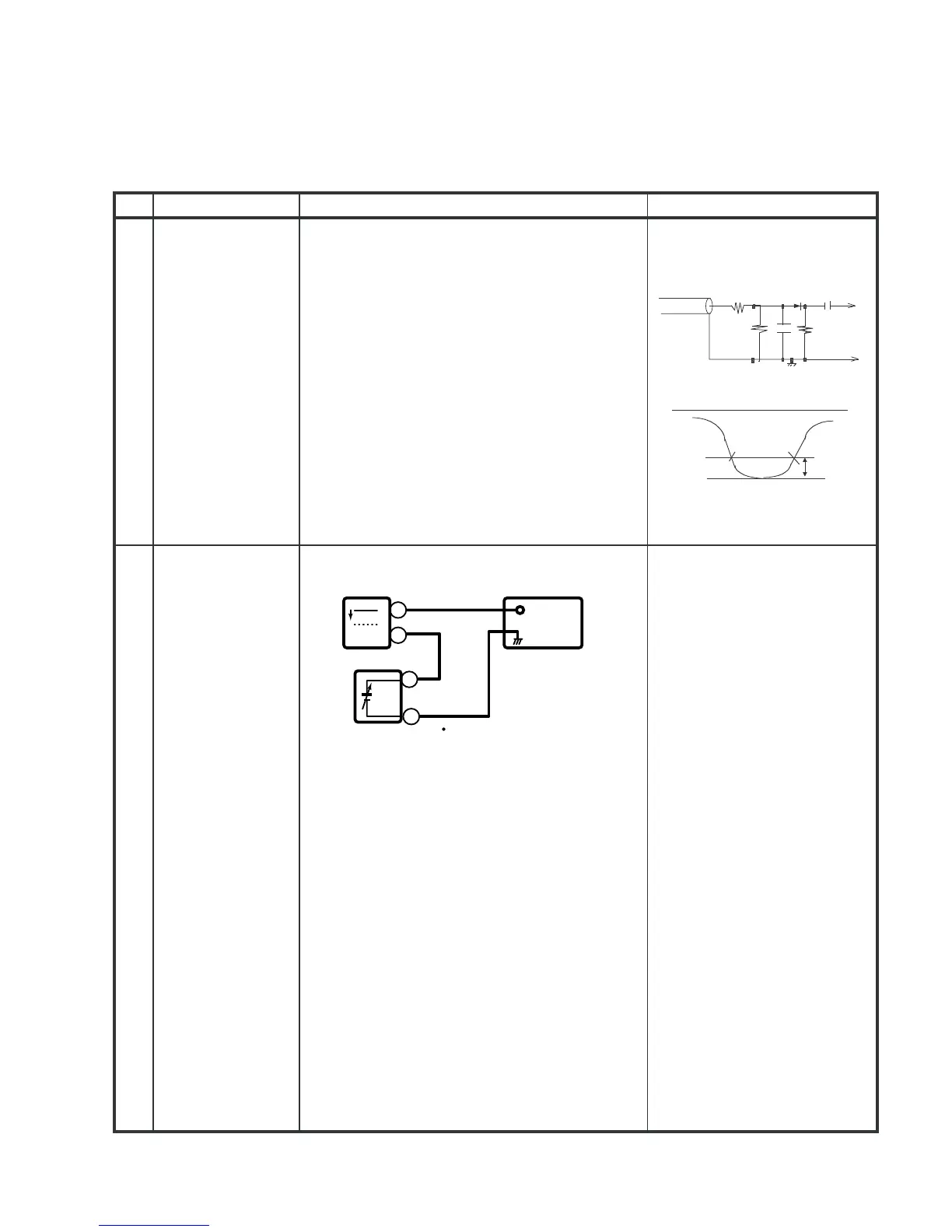
2
Bias box: About 4.5 V
Oscilloscope
0.1V
TV Set
Bias box
TP201
+
+
Fig. 3-1
E-9 CH
PC
10k
100k
1n60
75ohm
IF OUT
-1.5+/-0.8dB
1000p
1000p
Oscilloscope
Fig.1
Fig.2
-
-
 Loading...