21F-PD250 / 21F-PT220 / 21F-PA18 / 21F-PA18(B)
3 – 20
6. HORIZONTAL, VERTICAL, DEFLECTION LOOP and FOCUS ADJUSTMENT
7. PAL CHROMA ADJUSTMENT
No.
Adjustment point
Adjustment procedure/conditions Waveform and others
H-SHIFT
(I
2
C BUS
CONTROL)
(to be done
after purity adj)
V-SHIFT
(I
2
C BUS
CONTROL)
(to be done
after purity adj)
1
2
V-SIZE
(I
2
C BUS
CONTROL)
(to be done
after purity,
V-shift adj)
3
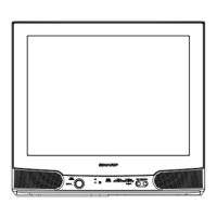
1) Receive Monoscope Pattern Signal (PAL 50Hz).
2) Choose the service data V13.
3) Adjust the V13 bus data to have a balance position to
spec of A=B (as attach drawing).
4) If cannot make it to A=B, adjust from the best point so
that B slightly smaller than A.
1) Receive Monoscope Pattern Signal (PAL 50Hz).
2) Choose the service data V12.
3) Adjust the V12 bus data to have a most acceptable
vertical position, the monoscope pattern should be
Balance in vertical position.
Note: B line (Monoscope middle line) must same or
nearest higher position to the A mark (Tube middle
mark), refer to the attach drawing.
1) Receive Monoscope Pattern Signal (PAL 50Hz).
2) Choose the service data V11.
3) Adjust V11 bus data until the overscan become
10 1.5%.
SUB-
SHARPNESS
4
FOCUS
5
Focusing Point
(middle of center
and edge of
monoscope
pattern)
1) Confirm Service data V08 & V32 are 38.
1) Receive the "Monoscope Pattern" signal.
2)
Press R/C to set Picture NORMAL condition.
3) Adjust the focus control to get the best focusing.
Caution 1: Pls aging TV more than 10 minutes before
adjustment
Caution 2: for H-shift & V-shift & V-size adj, after adj
pls switch to Monoscope pattern signal (NTSC 60 Hz)
to confirm all positions are the same.
No.
Adjustment point
Adjustment procedure/conditions Waveform and others
SUB COLOUR
(I
2
C BUS
CONTROL)
(to be done
after sub-
picture, sub-
tint adj)
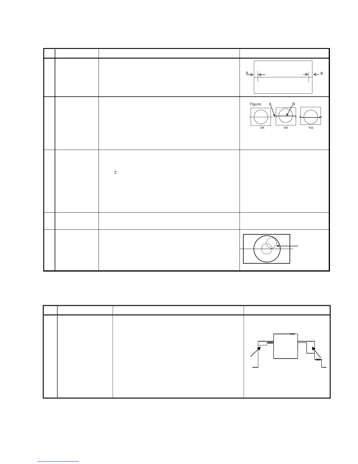
1) Receive the “PAL Colour Bar” signal.
2) Press R/C to set Picture Normal condition.
3) Connect the oscilloscope to R-Amp Transistor
Base(JUMPER 401).
Range : 100mV/Div (AC)
(Using 10:1 Probe)
Sweep Time : 10 msec/Div
4) Using the R/C call V05 in SERVICE mode. Ad-
just V05 bus data, so that the 75% White & Red
portions of PAL Colour Bar be at the same level
shown as Fig 1-1.
5) Clear the SERVICE mode.
1
Fig. 1-1
Cy G B
W
Y 100% W Mg R
75%
 Loading...