Do you have a question about the Sharp LC-22LE320 and is the answer not in the manual?
Essential safety measures for service technicians to follow during TV repair and servicing.
Critical warnings regarding fire risk from incorrect fuse replacement and shock hazards.
Guidelines on applying lead-free wire solder for PWB repair to avoid damage or accidents.
Recommendations for using lead-free solder, including soldering bit care and part replacement.
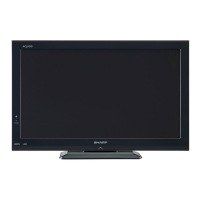
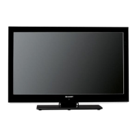
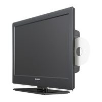
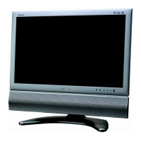
Detailed technical specifications for various LCD Colour TV models.
User guide on operating the TV using the remote control and front panel buttons.
Physical dimensions of the TV models including stand and wall mounting VESA compatibility.
Step-by-step instructions for disassembling the TV, covering panel removal and component board access.
Details on OSD menu settings and alignment methods for display adjustments.
Instructions on how to enter and navigate the factory service mode menu.
Step-by-step guide for upgrading the TV firmware using USB flash drives.
Diagnostic table for common power unit and main unit issues.
Troubleshooting steps for problems related to no sound output from speakers or terminals.
Diagnostic steps for display problems, including LVDS signal and control signal checks.
Detailed technical information on key ICs like MT5363LICG, Si2163, and MAX3232EEUE.
Functional block diagram of the main board for different TV sizes.
Component layout diagrams for the main unit's printed wiring board for 19”, 22”, and 26” models.
Component layout diagrams for the power unit's printed wiring board for the 26” model.
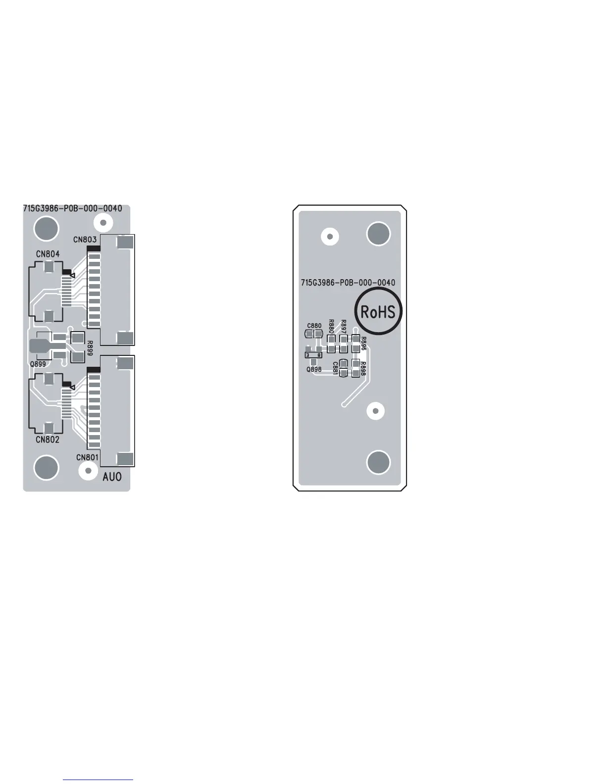
Component layout diagrams for the key unit's printed wiring board.
Detailed schematic diagrams for the main unit, including power and other critical circuits.
Comprehensive list of all spare parts with TPV Code, SHARP Code, and description.