63
LC-19LE510
LC-22LE510
LC-24LE510
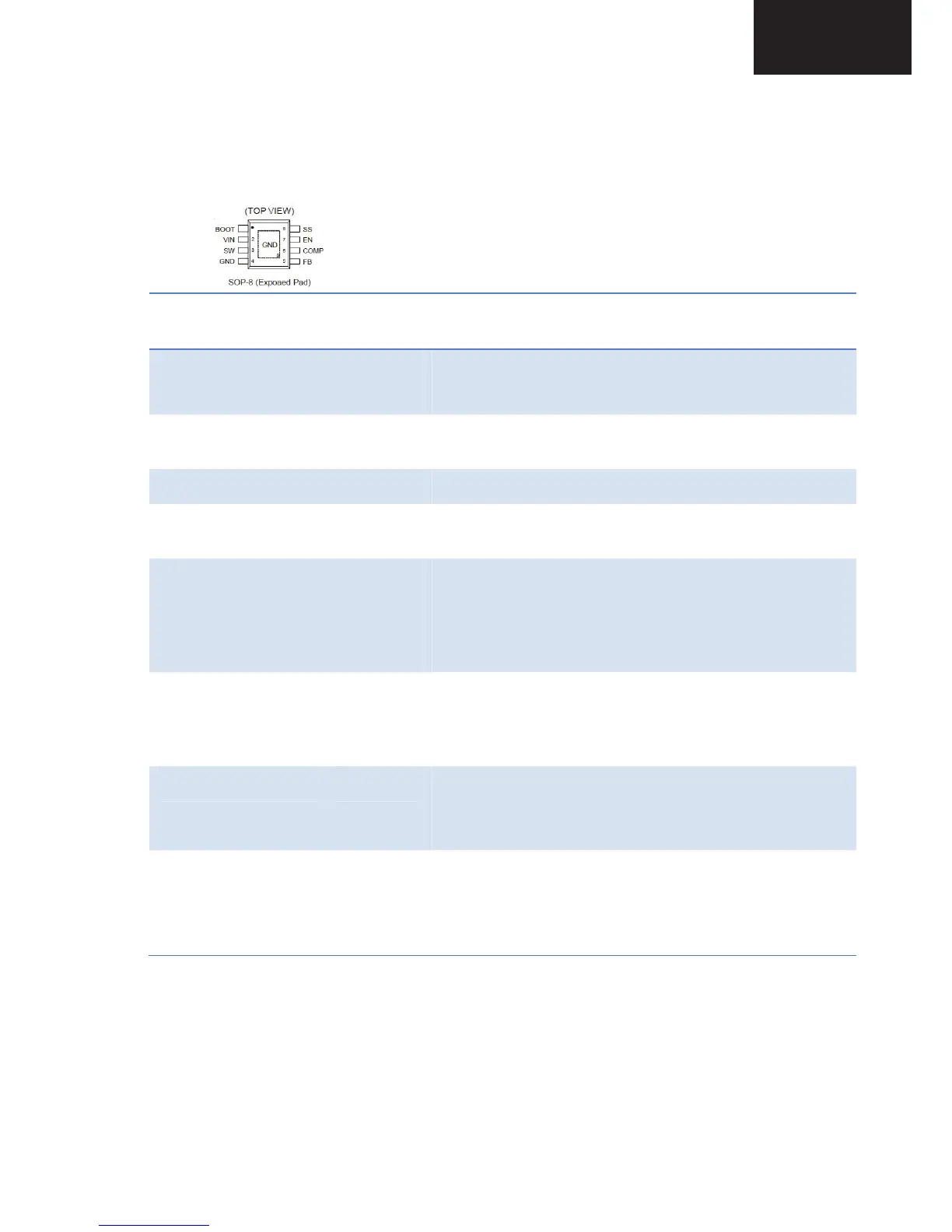
19.3. Pinning
Pin No. Pin
Name
Description
1
BOOT
Bootstrap for high-side gate driver. Connect a 0.1μF or
greater ceramic capacitor from BOOT to SW pins.
2
VIN Input Supply 4.5V to 23V. Must bypass with a suitably
large ceramic capacitor.
3
SW Phase Node--Connect to external L-C filter..
4, 9 (Exposed
Pad)
GND Ground.
5
FB Feedback Input pin is connected to the converter output.
It is used to set the output of the converter to regulate to
the desired value via an internal res divider. For an
adjustable output, an external res divider is connected to
this pin.
6
COMP Compensation Node. COMP is used to compensate the
regulation Control loop. Connect a series RC network
from COMP to GND. In some cases, an additional
capacitor from COMP to GND is required.
7
EN Enable Input Pin. Logic high enables the converter; a
logic low forces the RT8253A into shutdown mode.
Attach this pin to VIN with a 100kΩ pull up resistor for
automatic startup.
8
SS Soft-Start Control Input. SS controls the soft-start period.
Connect a capacitor from SS to GND to set the soft-start
period. A 0.1μF capacitor sets the soft-start period to
13.5ms.
18.3
 Loading...