SAFETY PRECAUTION
IMPORTANT SERVICE SAFETY PRECAUTION
.............i
Precautions for using lead-free solder ...............ii
CHAPTER 1. SPECIFICATIONS
[1] SPECIFICATIONS .........................................1-1
CHAPTER 2. OPERATION MANUAL
[1] OPERATION MANUAL .................................. 2-1
CHAPTER 3. DIMENSIONS
[1] DIMENSIONS ................................................ 3-1
CHAPTER 4. REMOVING OF MAJOR PARTS
[1] REMOVING OF MAJOR PARTS
LC-26SA1E/RU.............................................. 4-1
[2] REMOVING OF MAJOR PARTS
LC-32SA1E/RU.............................................. 4-5
CHAPTER 5. ADJUSTMENT PROCEDURE
[1] After replacement of any PWB and/or IC for
repair, note the following. ............................... 5-1
[2] SOFTWARE UPDATING................................ 5-1
[3] Entering and exiting the adjustment pro-
cess mode.................................................... 5-11
[4]
Remote controller key operation and descrip-
tion of display in adjustment process mode
....... 5-11
[5] Adjustment process mode menu.................. 5-12
[6] Special features............................................ 5-13
[7] Video signal adjustment procedure.............. 5-14
[8] White Balance Adjustment........................... 5-16
[9] QS Temperature NVM Data Con?rmation......5-17
[10] Initialization to factory settings.....................5-17
[11] Lamp error detection ...................................5-18
[12] Public Mode (Hotel Mode)...........................5-18
CHAPTER 6. TROUBLESHOOTING TABLE
[1] TROBLESHOOTING TABLE.........................6-1
CHAPTER 7. MAJOR IC INFORMATIONS
[1] MAJOR IC INFORMATIONS .........................7-1
CHAPTER 8. OVERALL WIRING DIAGRAM/BLOCK
DIAGRAM
[1] OVERALL WIRING DIAGRAM......................8-1
[2] BLOCK DIAGRAM.........................................8-3
[3] POWER BLOCK DIAGRAM..........................8-5
CHAPTER 9. PRINTED WIRING BOARD
[1]
OPERATION UNIT PRINTED WIRING BOARD
........9-1
[2]
R/C, LED UNIT PRINTED WIRING BOARD
........9-2
[3] MAIN UNIT PRINTED WIRING BOARD........9-3
[4] AV UNIT PRINTED WIRING BOARD..........9-11
[5] POWER UNIT PRINTED WIRING BOARD......9-17
[6] TUNER UNIT PRINTED WIRING BOARD......9-21
CHAPTER 10. SCHEMATIC DIAGRAM
[1]
DESCRIPTION OF SCHEMATIC DIAGRAM
......10-1
[2] SCHEMATIC DIAGRAM..............................10-2
Parts Guide
SERVICE MANUAL
CONTENTS
Parts marked with " " are important for maintaining the safety of the set. Be sure to replace these parts with specified ones for maintaining the
safety and performance of the set.
This document has been published to be used for
after sales service only.
The contents are subject to change without notice.
TopPage
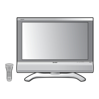
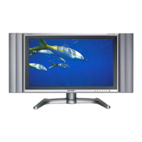
LC-26SA1E/RU, LC32SA1E/RU
LCD COLOUR TELEVISION
LC-32SA1E/RU
LC-26SA1E/RU
MODELS
In the interests of user-safety (Required by safety regulations in some countries) the set should be restored to its orig-
inal condition and only parts identical to those specified should be used.
No. S66U9LC26SA1E