LC-26SA1E/RU, LC-32SA1E/RU
4 – 1
LC-26SA1E
Service Manual
CHAPTER 4. REMOVING OF MAJOR PARTS
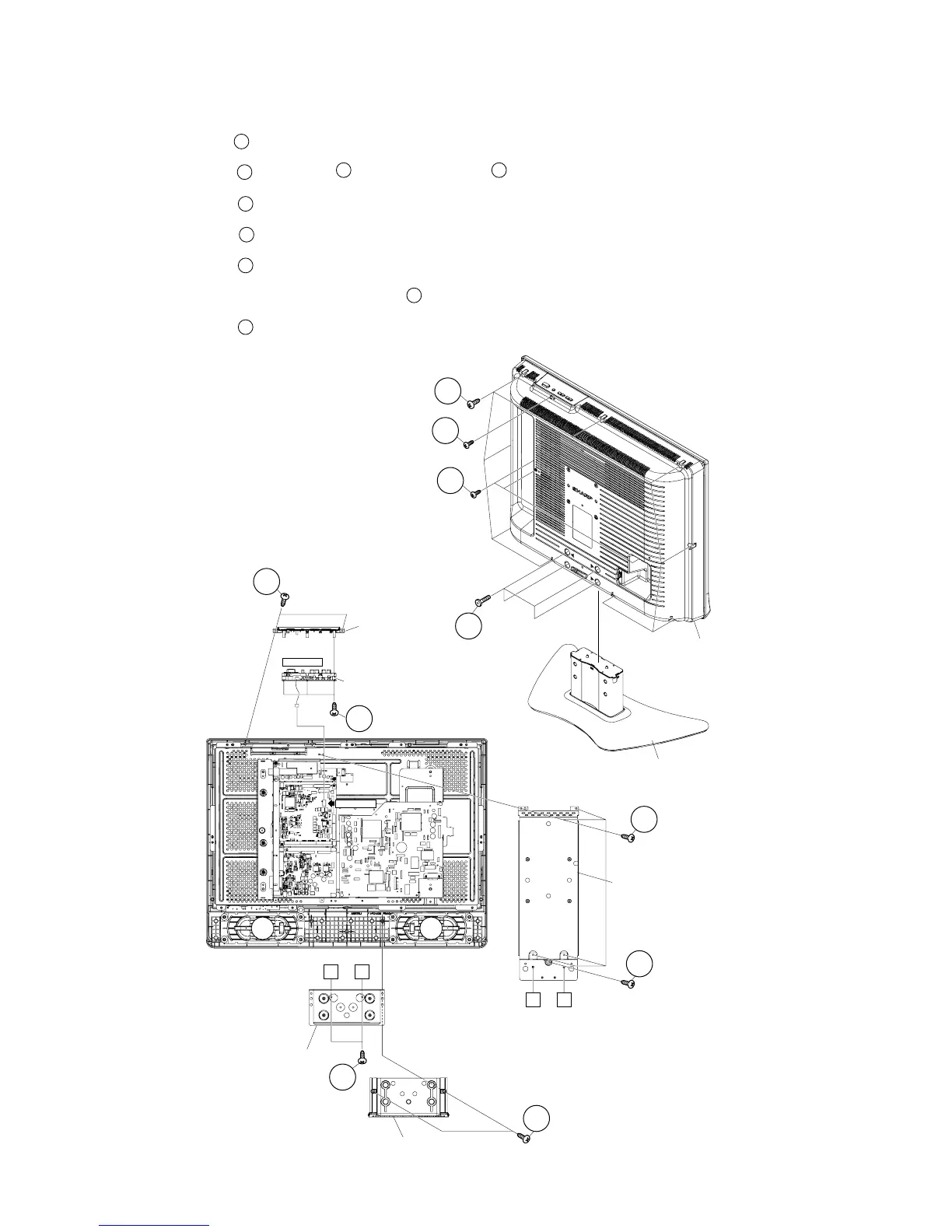
[1] REMOVING OF MAJOR PARTS LC-26SA1E/RU
1. Remove the 4 lock screws . Detach the Stand.
2. Remove the 3 lock screws . 1 lock screw and the 9 lock screws . Detach the Rear Cabinet.
3. Remove the 2 lock screws and detach the Bottom Cover.
4. Remove the 2 lock screws and detach the Stand Angle.
5. Remove the 5 lock screws and detach the Center Angle.
6. Disconnect the KM connector. Remove the 2 lock screws and detach the Top Cover Ass’y.
7. Remove the 3 lock screws and detach the KEY Unit.
1
2
3 4
5
6
7
8
9
Rear Cabinet
Stand
1
2
3
4
Stand Angle
Bottom Cover
Center Angle
7
7
5
Key Unit
Top Cover Ass'y
8
9
KM(P2302)
KM(P169)
A B
A B
6
 Loading...