LC-26SA1E/RU, LC-32SA1E/RU
5 – 14
[7] Video signal adjustment procedure
* The adjustment process mode menu is listed in Section 5.
1. Signal check
1. Signal generator level adjustment check (Adjustment to the specified level)
2. EnterinEnter the adjustment process mode
1. Enter the adjustment process mode according to Section 3.
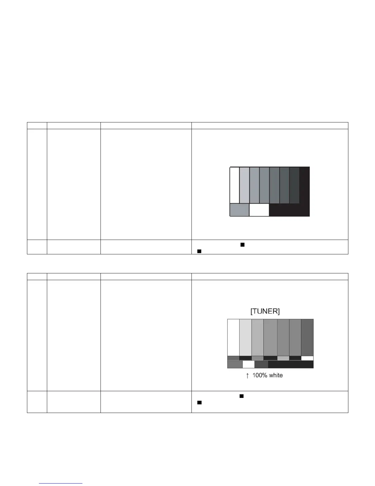
3. RF AGC adjustment
4. RF AGC Adjustment (SMPTE RF SIGNAL- Alternative Method)
•Composite signal PAL : 0.7Vp-p ±0.02Vp-p (Pedestal to white level)
•15K component signal : Y level 0.7Vp-p ±0.02Vp-p (Pedestal to white level)
(50 Hz) PB, PR level 0.7Vp-p ±0.02Vp-p
Adjustment point Adjustment Conditions Adjustment procedure
1 Setting [Signal]
PAL
Sprit Field Colour Bar
RF signal UV
[Terminal]
TUNER
•Feed the PAL Sprit Field colour bar signal to TUNER.
Signal level: 52 dB µV +0dB , -1dB (75Ω LOAD)
2 Auto adjustment
performance
Adjustment process
Page3
Bring the cursor on [ RF AGC ADJ] and press [OK]
[ RF AGC ADJ OK] appears when finished.
Adjustment point Adjustment Conditions Adjustment procedure
1 Setting [Signal]
PAL
SMPTE Field Color Bar
RF signal UV
[Terminal]
TUNER
•Feed the PAL SMPTE color bar signal (E-12ch) to TUNER.
Signal level: 52 ±1dB µV (75Ω LOAD)
2 Auto adjustment
performance
Adjustment process
Page6
Bring the cursor on [ RF AGC ADJ] and press [OK].
[ RF AGC ADJ OK] appears when finished.
[RF Signal]
㸡100% white
 Loading...