OUTLINE
This model is based on the LC-32LE700E/RU/S, LC-40LE700E/RU/S, LC-46LE700E/RU/S and is changed some
parts. This Service Manual covers the modifications alone. For the other points, refer to the LC-32LE700E/RU/S,
LC-40LE700E/RU/S and LC-46LE700E/RU/S (No. S89B4LC32L700) Service Manual.
SERVICE MANUAL
Parts marked with " " are important for maintaining the safety of the set. Be sure to replace these parts with specified ones for maintaining the
safety and performance of the set.
This document has been published to be used for
after sales service only.
The contents are subject to change without notice.
OUTLINE AND DIFFERENCES FROM BASE MODEL
OUTLINE.............................................................i
DIFFERENCES FROM BASE MODEL..............ii
SAFETY PRECAUTION
IMPORTANT SERVICE SAFETY PRE-
CAUTION...........................................................v
Precautions for using lead-free solder ..............vi
End of life disposal...........................................vii
CHAPTER 1. SPECIFICATIONS
[1] SPECIFICATIONS ......................................... 1-1
CHAPTER 2. OPERATION MANUAL
[1] OPERATION MANUAL .................................. 2-1
CHAPTER 3. DIMENSIONS
[1] DIMENSIONS ................................................ 3-1
CHAPTER 4. ADJUSTMENT PROCEDURE
[1] ADJUSTMENT PROCEDURE....................... 4-1
CHAPTER 5. TROUBLESHOOTING TABLE
[1] TROUBLESHOOTING TABLE....................... 5-1
CHAPTER 6. MAJOR IC INFORMATIONS
[1] MAJOR IC INFORMATIONS.......................... 6-1
CHAPTER 7. OVERALL WIRING/SYSTEM BLOCK
DIAGRAM
[1] OVERALL WIRING DIAGRAM (LC-
32LE600E/RU/S)...........................................7-1
[2] OVERALL WIRING DIAGRAM (LC-
40LE600E/RU/S)...........................................7-2
[3] OVERALL WIRING DIAGRAM (LC-
46LE600E/RU/S)...........................................7-3
[4] SYSTEM BLOCK DIAGRAM (LC-
32LE600E/RU/S)...........................................7-4
[5] SYSTEM BLOCK DIAGRAM (LC-
40LE600E/RU/S)...........................................7-5
[6] SYSTEM BLOCK DIAGRAM (LC-
46LE600E/RU/S)...........................................7-6
CHAPTER 8. PRINTED WIRING BOARD ASSEM-
BLIES
[1] MAIN UNIT ....................................................8-1
CHAPTER 9. SCHEMATIC DIAGRAM
[1] DESCRIPTION OF SCHEMATIC DIA-
GRAM............................................................9-1
[2] SCHEMATIC DIAGRAM................................9-2
Parts Guide
TopPage
CONTENTS
LC-32/40/46LE600E/RU/S (1st Edition)
No. S89B5LC32L600
MODELS
LC-32LE600E/RU/S
LC-40LE600E/RU/S
LC-46LE600E/RU/S
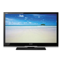
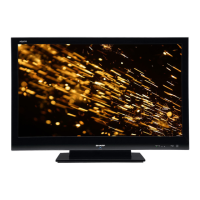
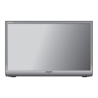
LCD COLOUR TELEVISION
In the interests of user safety (required by safety regulations in some countries) the set should be restored to its
original condition and only parts identical to those specified should be used.









 Loading...