LC-32/40/46LE600E/RU/S (1st Edition)
4 – 10
13. Functional explanation of STANDBY CAUSE
13.1. [display method]
It is displayed in the top page of the process adjustment mode. (Page displayed first when entering process mode)
13.2. [Content of display]
1. NORMAL STANDBY CAUSE
The reason that became a power-off by the specification of usual use and the main body is displayed.
(Only the one latest) It is not displayed when power supply OFF is carried out with remote control.
2. ERROR STANDBY CAUSE
When main CPU becomes a power-off detecting some abnormalities, the use time of the set at the time of the reason and the power-off is dis-
played five times.
When time information can be acquired from digital broadcasting, the date and time when the error occurs at the same time is recorded, displayed
and when time information cannot be acquired, it becomes the above-mentioned display.
“00” is displayed when abnormality has not been detected even once.
14. Lamp error detection
1. Function description
This LCD colour television has a function (lamp error detection) to be turned OFF automatically for safety when the lamp or lamp circuit is abnor-
mal.
If the lamp or lamp circuit is abnormal, or some other errors happen, and the lamp error detection is executed, the following occur.
1) The main unit of television is turned OFF about 5 seconds after it is turned ON.
(The power LED on the front side of TV turns from green to red.)
2) If the situation “1” happens 5 times sequentially, the power is turned on (relay is turned ON).
However, the backlight is not turned on, and then the relay is turned OFF after 5 to 6 seconds. (The power LED remains red.)
2. Countermeasures
When television is turned OFF by the lamp error detection mentioned above, it enters the adjustment process with the power LED red.
Entering the adjustment process, turns OFF the error detection and turns ON TV.
This enables the operation check to detect errors in the lamp or lamp circuit.
Check whether “STANDBY CAUSE” on line 7, page 1/8 of the adjustment process is “1B”. it indicates the lamp error detection was executed.
After confirming that the lamp or lamp circuit is normal, reset the lamp error counter pushing “OK” in the R/C.
After resetting counter the green bar appears on Screen.
3. Reset standby cause error list
After confirming that the lamp error counter has been erased, select “ERROR RESET”, page 1/8 of the adjustment process and select YES using
the right cursor. For execute press “OK” in the R/C and the label “***OK***” appears on Screen.
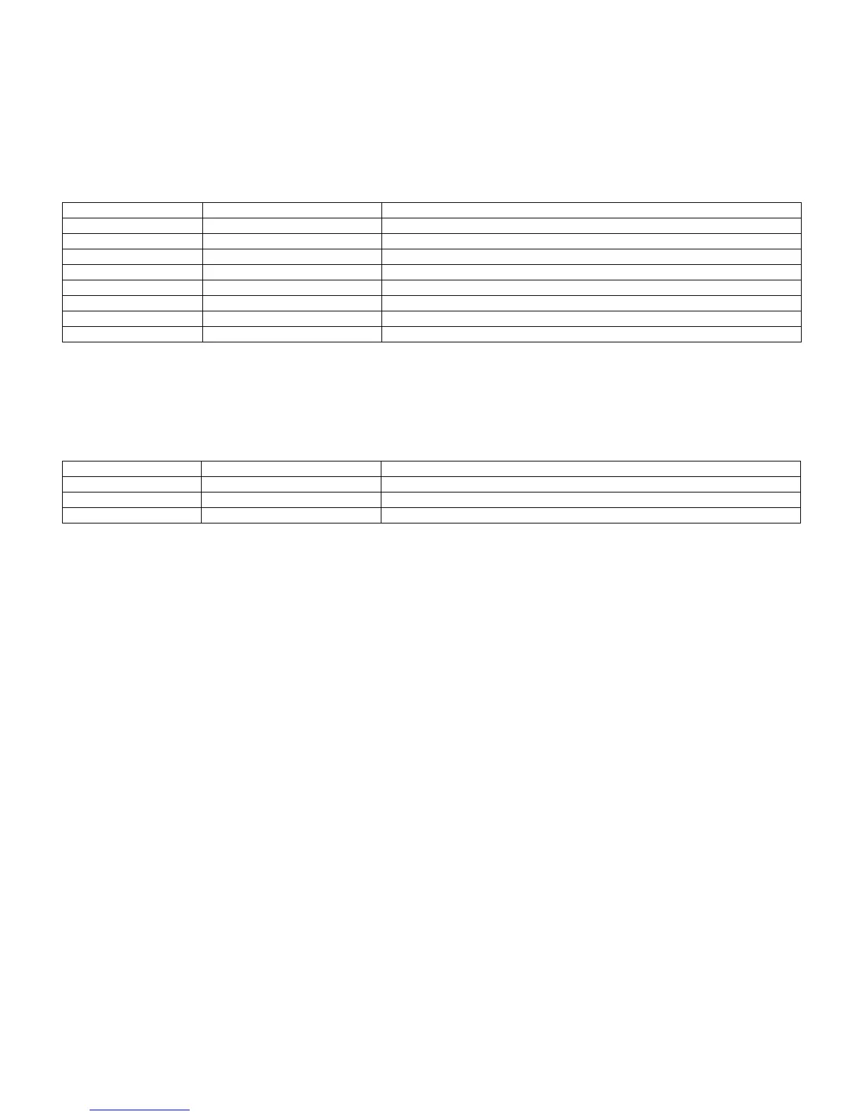
Display code Display character string Reason
00 00 00 00 00 00 When based on No error
0x01 1 RC_STANDBY When based on RC Standby OFF
0x05 5 PC_OUT_OF_RANGE When based on out of range for pc OFF
0x06 6 NO_OPERATION When based on non-operated OFF
0x07 7 NO_SIGNAL When based on non-signal OFF
0x0A a SLEEP_TIMER When based on an sleep-timer OFF
0x0C c RS232C When based on the command from RS232C (standby)
0x18 18 AV_LINK When based on the command from AV-LINK (standby)
Display error code Display character string Reason
0x1A 1a TEMP_ERROR When temperature (high temperature) is abnormal.
0x1B 1b LAMP_ERROR When lamp is abnormal
0x1C 1c POWER_ERROR When power module is abnormal status.
 Loading...