38
E
Controlling the Monitor with a PC (RS-232C)
n
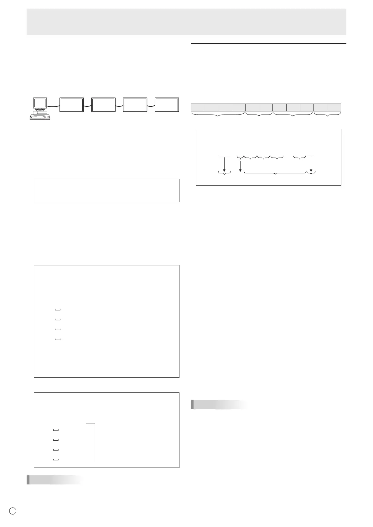
Repeater control
This system has a function to allow setting of multiple
monitors connected in a daisy chain using a single command.
This function is called repeater control. You can use Repeater
control function without assigning ID numbers.
Set 1
Set 2 Set
et 4
* If monitors are connected as shown above, you can
execute a command like “Set all monitors’ input settings to
D-SUB[RGB]”.
n
Repeater control command
Repeater control is achieved by setting the FOURTH
CHARACTER of the parameter to “+”.
Example:
VOLM030 + ←
Sets volume of all monitors to 30.
In repeater control, responses are returned by all the
connected monitors.
If you want to determine that a value has been returned by a
specic set, assign ID numbers to each monitor in advance.
When some monitors do not return their responses, the
probable cause is that the monitors could not receive the
command or command processing is not complete. Do not
send a new command.
Example: (When 4 monitors are connected, and
assigned ID numbers: 1 through 4)
VOLM030 +
WAIT
OK
001
OK
002
OK
003
OK
004 ← If 4 monitors are connected in
a chain, reliable operation can
be ensured by sending a new
command only after a reply
has been returned by 4th (last)
monitor.
Repeater control can also be used for reading settings.
Example:
VOLM ? ? ? +
WAIT
10
001
Volume settings for all
monitors are returned.
20
002
30
003
30
004
TIPS
• If repeater control is used during ID designation (IDSL,
IDLK), the ID designation is canceled.
Setting of the GAMMA user data
n
To transfer the GAMMA user data
Use the user data transfer commands (UGRW, UGGW and
UGBW). For each of the R, G and B colors, divide the total
512 pieces of user data into 16 blocks, and transfer 32 pieces
of data with each command.
C1 C2 C3 C4 P1 P2 P3 P4
S1 S2
Command field
Block number (01 to 16)
Data fieldChecksum field
Example: To transfer the data of block 1 (0 to 31 levels)
of red (R) data
UGRW01000000010002 … 0031C0
Command
Block number
32 pieces of data Checksum
One piece of data consists
of 4 digits.
* If data is less than 4 digits, add a “0” (zero) to make it 4
digits.
* The checksum eld is the character string (ASCII) data of
lower-order one byte which indicates the sum of the block
number and 32 pieces of data in hexadecimal (0 to F).
n
Saving the GAMMA user data
Use the user data save command (UGSV) to save the
transferred user data in the monitor.
If the data is not saved, it will be cleared when:
• The main power switch is off
• POWER SAVE MODE is ON and the monitor enters
standby mode
n
Activating the GAMMA user data
To activate the transferred user data, select USER for GAMMA
of the PICTURE menu, or send the corresponding RS-232C
command.
n
Checking the GAMMA user data
Use the user data read commands (UGRR, UGGR and
UGBR) to return 512 pieces of user data for each of the R,
G and B colors. Divide the data into 16 blocks and return 32
pieces of data with each command. The value to be returned
is not the value stored in the monitor, but the value in the
temporary memory for display. (These values are the same
when the user data save command (UGSV) above has been
sent.)
TIPS
• The user data is not initialized by RESET of the PICTURE
menu. To initialize the user data, use ALL RESET of the
FUNCTION menu.
The GAMMA user data initialize command (UGRS) allows
the initialization of the user data only.
 Loading...