R-9HlO
TEST PROCEDURES (CONT’D)
PROCEDURE
LETTER
COMPONENT TEST
I
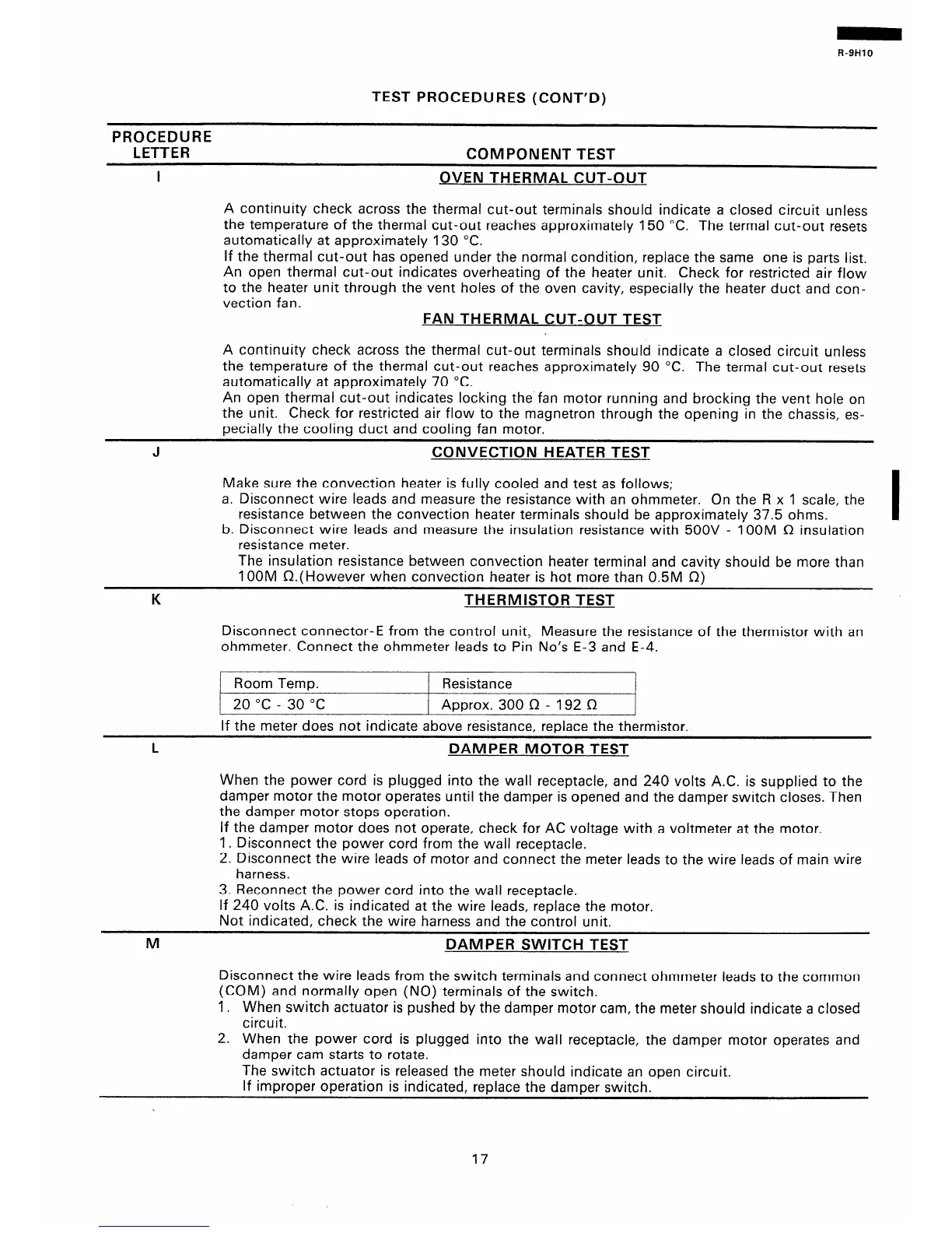
OVEN THERMAL CUT-OUT
A continuity check across the thermal cut-out terminals should indicate a closed circuit unless
the temperature of the thermal cut-out reaches approximately 150 “C. The termal cut-out resets
automatically at approximately 130 “C.
If the thermal cut-out has opened under the normal condition, replace the same one is parts list.
An open thermal cut-out indicates overheating of the heater unit. Check for restricted air flow
to the heater unit through the vent holes of the oven cavity, especially the heater duct and con-
vection fan.
FAN THERMAL CUT-OUT TEST
A continuity check across the thermal cut-out terminals should indicate a closed circuit unless
the temperature of the thermal cut-out reaches approximately 90 “C. The termal cut-out resets
automatically at approximately 70 “C.
An open thermal cut-out indicates locking the fan motor running and brocking the vent hole on
the unit. Check for restricted air flow to the magnetron through the opening in the chassis, es-
pecially the cooling duct and cooling fan motor.
CONVECTION HEATER TEST
Make sure the convection heater is fully cooled and test as follows;
a. Disconnect wire leads and measure the resistance with an ohmmeter. On the R x 1 scale, the
resistance between the convection heater terminals should be approximately 37.5 ohms.
b. Disconnect wire leads and measure the insulation resistance with 500V - 1 OOM n insulation
resistance meter.
The insulation resistance between convection heater terminal and cavity should be more than
1 OOM n.( However when convection heater is hot more than 0.5M n)
THERMISTOR TEST
Disconnect connector-E from the control unit, Measure the resistance of the thermistor with an
ohmmeter. Connect the ohmmeter leads to Pin No’s E-3 and E-4.
Room Temp.
Resistance
20 “C - 30 “C
Approx. 300 fI - 192 n
If the meter does not indicate above resistance, replace the thermistor.
L
DAMPER MOTOR TEST
When the power cord is plugged into the wall receptacle, and 240 volts A.C. is supplied to the
damper motor the motor operates until the damper is opened and the damper switch closes. Then
the damper motor stops operation.
If the damper motor does not operate, check for AC voltage with a voltmeter at the motor.
1. Disconnect the power cord from the wall receptacle.
2. Disconnect the wire leads of motor and connect the meter leads to the wire leads of main wire
harness.
3. Reconnect the power cord into the wall receptacle.
If 240 volts A.C. is indicated at the wire leads, replace the motor.
Not indicated, check the wire harness and the control unit.
M
DAMPER SWITCH TEST
Disconnect the wire leads from the switch terminals and connect ohmmeter leads to the common
(COM) and normally open (NO) terminals of the switch.
1. When switch actuator is pushed by the damper motor cam, the meter should indicate a closed
circuit.
2. When the power cord is plugged into the wall receptacle, the damper motor operates and
damper cam starts to rotate.
The switch actuator is released the meter should indicate an open circuit.
If improper operation is indicated, replace the damper switch.
17
 Loading...
