R-9H10
OVEN LAMP/SOCKET ASSEMBLY REMOVAL
1. Disconnect oven from power supply and remove
NOTE; NEUTRAL(WHITE) WIRES MUST BE
outer case cabinet.
CONNECTED TO THE TERMINAL WITH
2. Disconnect wire leads from lamp socket.
‘N’ MARK ON LAMP SOCKET.
3. Remove two(2) screws holding oven lamp to the
lamp mounting angle.
STOP SWITCH, UPPER LATCH SWITCH, LOWER LATCH SWITCH AND
MONITOR SWITCH REMOVAL
1. Disconnect oven from power supply and remove
outer case.
2. Remove control panel assembly, refer to “Control
Panel Removal”.
3. Discharge high voltage capacitor.
4. Disconnect wire leads from each of the switches.
5. Remove two (2) screws holding latch hook to oven
flange.
6. Remove latch hook assembly from oven flange.
7. Push downward on the one (1) stopper tabs hold-
ing each of the switches place.
8. Switches are free.
At this time latch lever will be free, do not lose it.
Re-install
1. Re-install latch lever and each switch in its place,
refer to Figure C-l.
2. Re-connect the wire leads to each switches and fuse
holder.
Refer to the pictorial diagram.
3. Secure the latch hook (with two (2) mounting
screws) to the oven flange.
4. Make sure that monitor switch is operating properly.
Refer to chapter “Test Procedure” and Adjustment
procedure.
STOP SWITCH, UPPER LATCH SWITCH, LOWER LATCH SWITCH AND
MONITOR SWITCH ADJUSTMENT
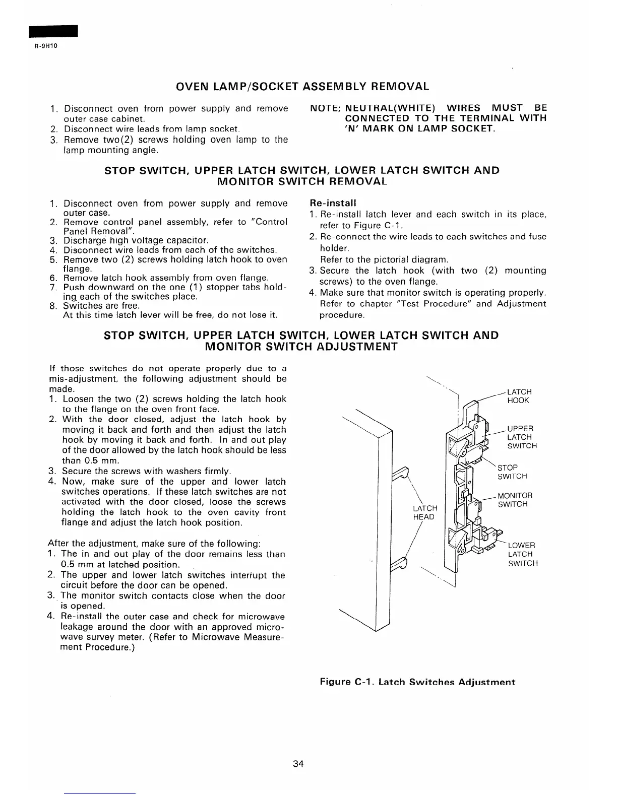
moving it back and forth and then adjust the latch
hook by moving it back and forth. In and out play
of the door allowed by the latch hook should be less
than 0.5 mm.
3. Secure the screws with washers firmly.
4. Now, make sure of the upper and lower latch
switches operations. If these latch switches are not
activated with the door closed, loose the screws
holding the latch hook to the oven cavity front
flange and adjust the latch hook position.
After the adjustment, make sure of the following:
1. The in and out play of the door remains less than
0.5 mm at latched position.
2. The upper and lower latch switches interrupt the
circuit before the door can be opened.
3.. The monitor switch contacts close when the door
is opened.
4. Re-install the outer case and check for microwave
leakage around the door with an approved micro-
wave survey meter. (Refer to Microwave Measure-
ment Procedure.)
\
If those switches do not operate properly due to a
mis-adjustment, the following adjustment should be
made.
1. Loosen the two (2) screws holding the latch hook
to the flange on the oven front face.
2. With the door closed, adjust the latch hook by
\,.
‘\
, LATCH
/ 5 HOOK
LATCH
HEAD
SWITCH
Figure C-l. Latch Switches Adjustment
34
 Loading...
