R-9HlO
TEST PROCEDURES (CONT’D)
PROCEDURE
LETTER
COMPONENT TEST
(6) Reconnect the oven to the power supply and check the sensor cook operation, proceed as
follows:
6-l. Fill approximately 200 milliliters (7.2 oz) of tap water in a 1000 milliliter measuring
cup.
6-2. Place the container on the center of tray in the oven cavity.
6-3. Close the door.
6-4. Touch SENSOR COOK pad and number 2 pad.
6-5. Touch Start pad. The control panel is in automatic Sensor operation.
6-6. The oven will turn off automatically when the water is boiling (bubling).
If new sensor does not operate properly, the problem is in the control unit.
CHECKING CONTROL UNIT
(1) Disconnect oven from power supply and remove outer case.
(2) Discharge the high voltage capacitor.
(3) Disconnect the wire leads from the cook relay.
(4) Disconnect the sensor connector that is mounted to lowe! portion of control panel.
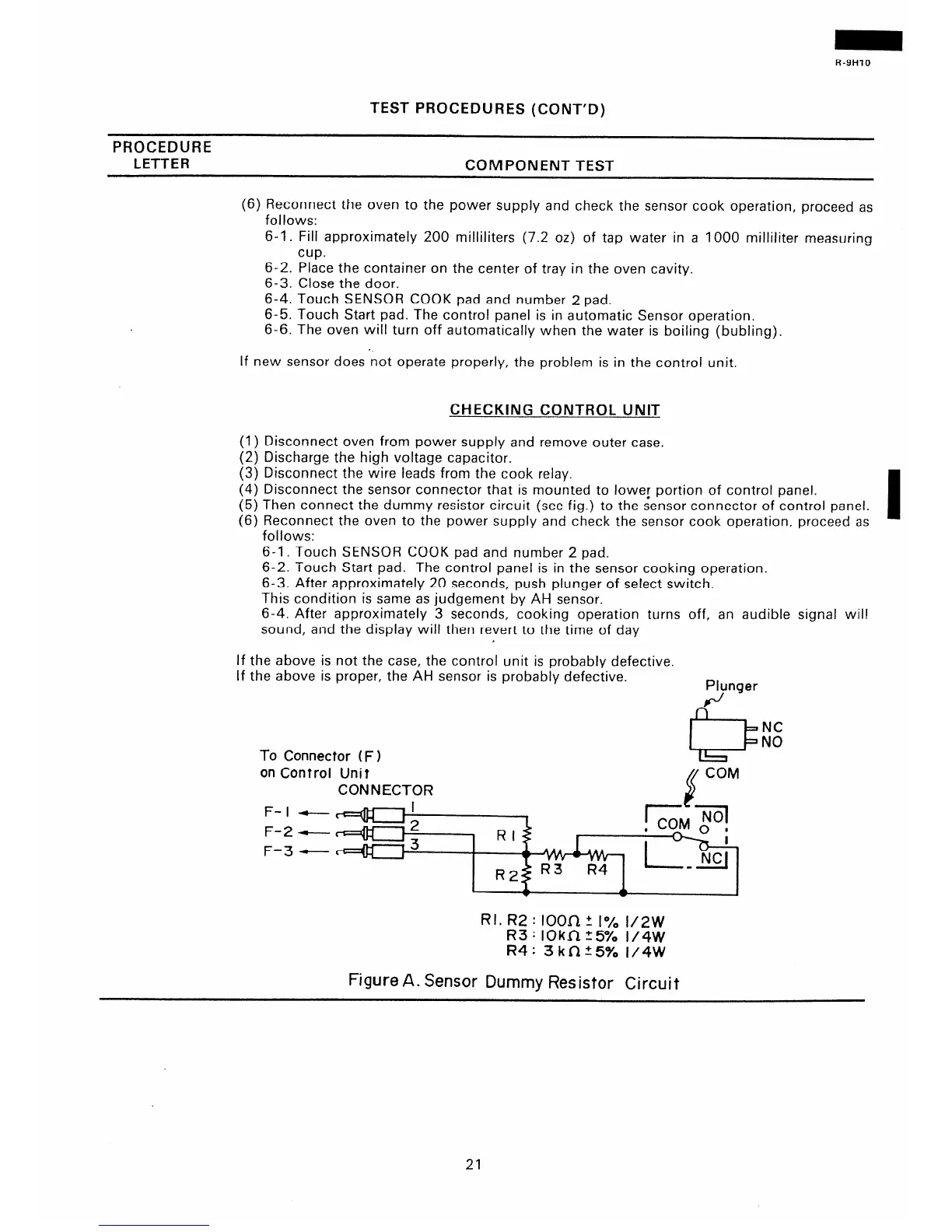
(5) Then connect the dummy resistor circuit (see fig.) to the sensor connector of control panel.
(6) Reconnect the oven to the power supply and check the sensor cook operation, proceed as
follows:
6-1. Touch SENSOR COOK pad and number 2 pad.
6-2. Touch Start pad. The control panel is in the sensor cooking operation.
6-3. After approximately 20 seconds, push plunger of select switch.
This condition is same as judgement by AH sensor.
6-4. After approximately 3 seconds, cooking operation turns off, an audible signal will
sound, and the display will then revert to the time of day
If the above is not the case, the control unit is probably defective.
If the above is proper, the AH sensor is probably defective.
Plynger
e
L
NC
NO
To Connector (F)
on Control Unit
/( CoM
CONNECTOR
2
F- I
F-2
F-3
f-
ccd#--) I
4-3 2
+jq---- 3
&ii=
* ;
IL?- -
NCI
RI. R2 : lOOa + 1% 1/2w
R3 : IOkn 5% I/4W
R4: 3kn:5% 1/4W
Figure A. Sensor Dummy Resistor Circuit
21
 Loading...
