R-9HlO
DESCRIPTION OF LSI
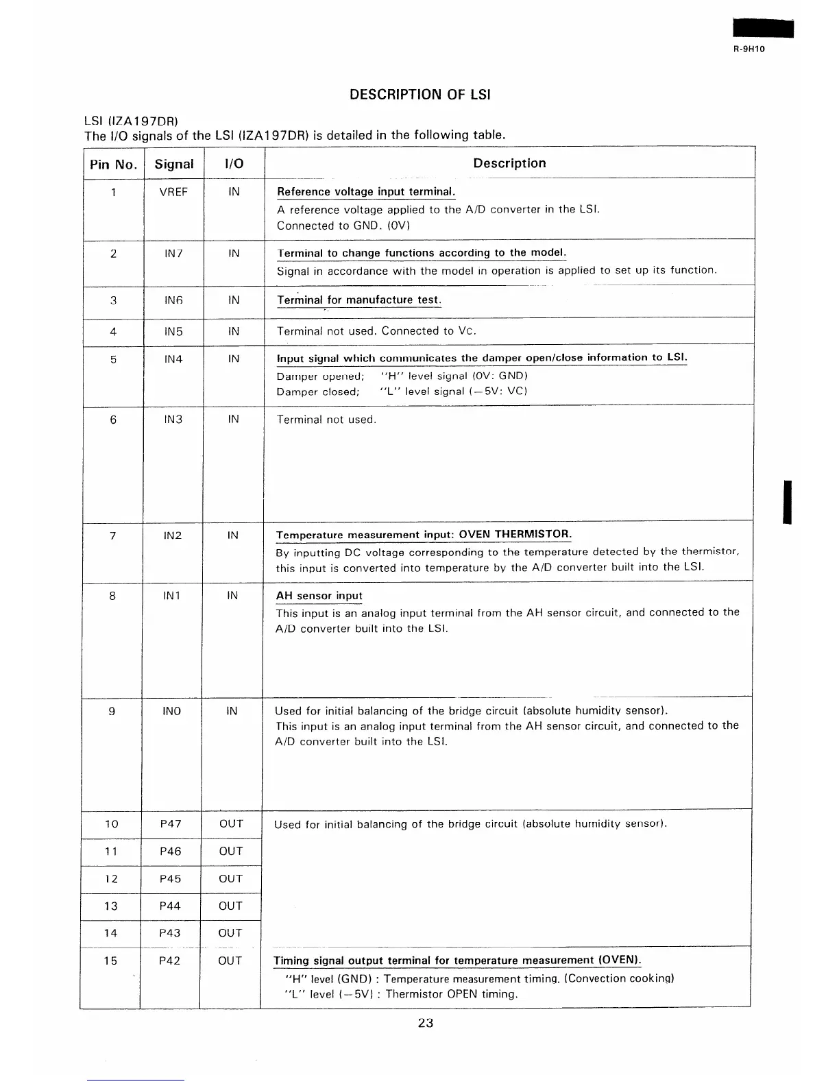
7e LSI (IZAl97DR) is detailed in the following table.
LSI (IZA197DR)
The I/O signals of 1
Signal
I/O
Description
Pin No.
VREF IN Reference voltage input terminal.
A reference voltage applied to the A/D converter in the LSI.
Connected to GND. (OV)
2 IN7 IN
Terminal to change functions according to the model.
Signal in accordance with the model in operation is applied to set up its function.
3 IN6 IN
Terminal for manufacture test.
-.
IN
Terminal not used. Connected to VC.
IN5
IN4
IN
4
5 input signal which communicates the damper open/close information to LSI.
Damper opened;
“H” level signal (OV: GND)
Damper closed;
“L” level signal (- 5V: VC)
IN
Terminal not used.
6 IN3
7
IN2 IN Temperature measurement input: OVEN THERMISTOR.
By inputting DC voltage corresponding to the temperature detected by the thermistor,
this input is converted into temperature by the A/D converter built into the LSI.
8
IN1 IN
AH sensor input
This input is an analog input terminal from the AH sensor circuit, and connected to the
A/D converter built into the LSI.
9
IN0
Used for initial balancing of the bridge circuit (absolute humidity sensor).
This input is an analog input terminal from the AH sensor circuit, and connected to the
A/D converter built into the LSI.
IN
P47
OUT
Used for initial balancing of the bridge circuit (absolute humidity sensor).
P46 OUT
10
11
12
P45
OUT
OUT
13 P44
14
P43 OUT
P42 OUT Timing signal output terminal for temperature measurement (OVEN).
“H” level (GND) : Temperature measurement timing. (Convection cooking)
“L” level (-5V) : Thermistor OPEN timing.
15
23
 Loading...
