9. MAINTENANCE VM-5S
-64-
9-3 VERIFICATION OF SPEED RELAY OPERATION
This procedure is used to test the display and contact output.
• Since SPEED RELAY contact will be output during the test, open the circuit between
the contacts and the connected system if necessary.
• Set each Bypass Switch to “OFF” position.
• When mounting this monitor unit in VM-5H3 or VM-5W1 Instrument Rack, set the
DANGER Bypass switch to “DISABL” position.
• The machine is not protected during operation test.
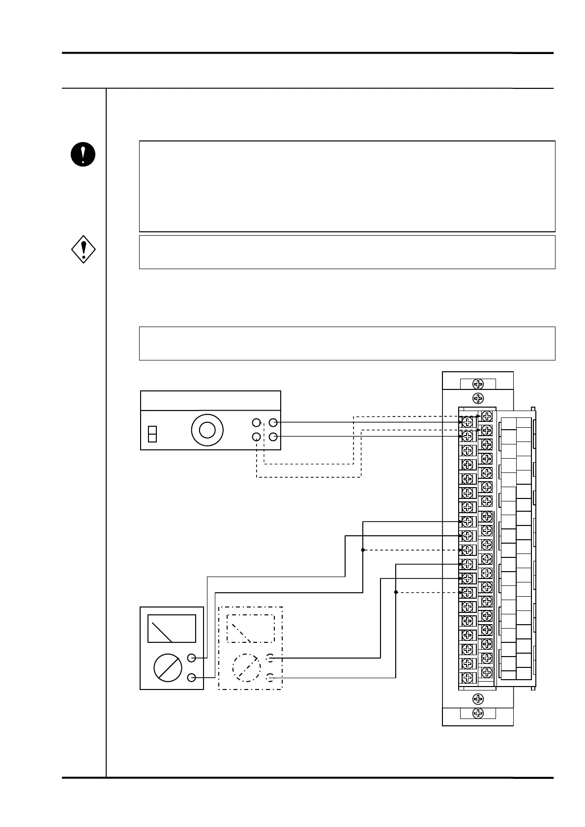
9-3-1 INTERCONNECTION (ex. VM-5G SINGLE UNIT INSTRUMENT RACK)
Connect a Synthesizer to the input/output terminals of the VM-5G Single Unit Instrument Rack
and test for connection between the SPEED RELAY contact output terminals.
• Connect to the SPEED RELAY contact output terminals under operation test.
Mandatory
Warning
A8
NC
A9
SR2
A10
NO
A11
NC
A12
SR1
A13
NO
A14
NC
A15
OK
A16
NO
A17
L1
A18
L2
19
FG
B8
NC
B9
SR4
B10
NO
B11
NC
B12
SR3
B13
NO
B14
SEQ
B15
COM
B16
P-S
B17
RES
B18
COM
B19
FLT
A1
A2
COM
A3
PWR
A4
REC
A5
REC-
A6
BUF
A7
COM
B1
B2
COM
B3
PWR
B4
REC
B5
REC
B6
BUF
B7
VM-5G Single Unit instrument Rack
Input/output terminal block
Tester Tester
NC
SR
□
NO
SR
□
NO
Synthesizer
NC
IN
COM.
IN
COM.
(The relay output mode must be set for both channels
if other than independent output is required.)
 Loading...