11
25A1104 (Rev.1)
FUNCTIONAL TEST
GENERAL INFORMATION LOOKUP TABLE
REQUIRED TEST EQUIPMENT (OR APPROVED EQUIVALENT OR SUPERIOR MODELS):
LISTENING TEST
Before completely disassembling the receiver, operate it to determine whether it is functioning normally and try to duplicate
the reported malfunction. Refer to pages 2 and 3 for operating instructions, troubleshooting, and specifications.
Review any customer complaint or request, and focus the listening test on any reported problem. The following, more ex-
tensive, functional tests require partial disassembly.
FUNCTIONAL TEST
NOTE: for these tests a tonekey generator must be used. If none is available, the unit must be opened and the tone
key must be disabled.
1. Apply +12 Vdc to the power input of the receiver (PS20).
2. Set up the Audio Analyzer as follows:
• Engage A-weighting filter
• Engage 30kHz LPF filter
3. Set up RF signal generator as follows:
• Frequency = F
o
(refer to the frequency tables on page 21)
• Amplitude = 0 dBm radiated
• FMrate = 1kHz
• Deviation = (see table next page)
RF Signal Generator Agilent E4420B
Audio Analyzer HP 8903B
Power Supply PS20
BNC (M) to BNC (M) cable (2) Shure PT1838A
BNC (F) to 1/4” adapter Shure PT1838C
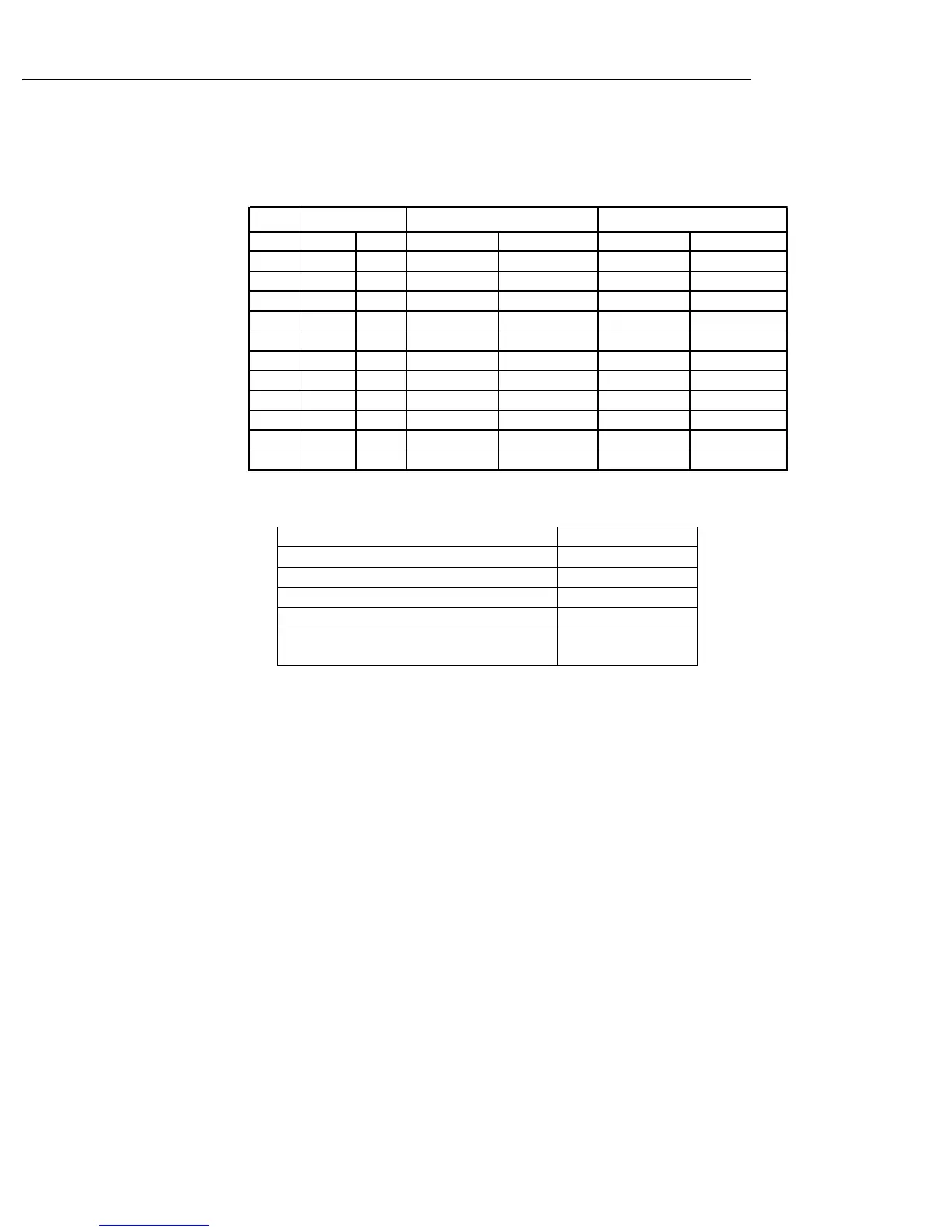
Matching UA820 Antenna Frequency
Dependent
Band Low High Low High 1st LO 2nd LO
H7 536 548 757.2 769.2 Fc+110.6 99.9MHz
K7 590 602 811.2 823.2 Fc+110.6 99.9MHz
M7 662 674 883.2 895.2 Fc+110.6 99.9MHz
M10 674 686 895.2 907.2 Fc+110.6 99.9MHz
P11 702 714 480.8 492.8 Fc-110.6 121.3MHz
Q11 740 752 518.8 530.8 Fc-110.6 121.3MHz
R11 770 782 548.8 560.8 Fc-110.6 121.3MHz
R12 794 806 572.8 584.8 Fc-110.6 121.3MHz
R10 800 812 578.8 590.8 Fc-110.6 121.3MHz
JB 806 810 584.8 588.8 Fc-110.6 121.3MHz
T10 854 865 632.8 643.8 Fc-110.6 121.3MHz
Fc (MHz) 1st Image Band (MHz) Local oscillators
 Loading...