16
25A1104 (Rev.1)
ALIGNMENT AND MEASUREMENT PROCEDURE
General notes
The following procedures are intended for a "bench" testing environment only.
The alignment procedure is sequential and does not change unless specified. Use an RG-178/U BNC male to unterminated cable for all
RF connections to the antenna inputs. Keep the test cables as short as possible (less than 3 feet in length). Include the insertion loss of the
cables and the connectors when performing all RF measurements. DC voltages may present at RF test points. Use DC blocks to protect
the test equipment, if necessary.
.
VOLTAGE REGULATION CHECK
With power applied properly, and the unit switched on, measure the DC voltages at the following test points. All test points are located
on the top side of the PCB. Refere to the component diagram.
ATE MODE SETUP AND USE
There are three different ATE mode test frequencies available in every frequency group, which are Flow, Fmid and Fhigh. The Fmid
frequency may not be the center of the band. It is selected for the best tuning of FL510 filter. Set the receiver into ATE mode by shorting
"ATE LE" to GND and then apply power to the receiver's DC jack. Press the channel button until you observe the 7-segment LED display
providing a selection of 1, 2, 3 for frequency groups H7,K7, M7, M10 and b, C, d for frequency groups P11, Q11, R11, R12, R10, JB, T10.
For example, when the 7-segment LED display's a "1" this is Flow, "2" is Fmid and "3" Fhigh. When you depress the channel button for
approximately 3-seconds the receiver enters into a micro controller reference level programming mode. When a "C" is displayed, press and
release the channel button several times so you can observe the 7-segment LED display providing a selection of a blinking C, A or P. The
"C" is to cancel the micro controller reference level-programming mode (do not confuse this "C" for Fmid for groups P11, Q11, R11, R12,
R10, JB, T10). The "A" is to set the audio LED reference level. The "P" is to set the predictive no switch level. Once the respective C, A or
P is selected and left blinking, the micro will perform the respective operation when the 7-segment LED display returns to the previous 1, 2
or 3 display.
INITIAL SETUP
Disabling diversity: For Channel A to be active, short TP2 to ground and connect TP3 to 3.3Vdc. For Channel B to be active, short TP3
to ground and connect TP2 to 3.3Vdc.
Set the receiver into ATE mode and to Fhigh. This sets the receiver to the highest operating frequency.(see table 4 for reference)
Test Points Voltages
TP_9V +9.0 ± 0.2 Vdc
TP_5V +5.0 ± 0.1 Vdc
TP_5VPLL +5.0 ± 0.2 Vdc
TP_3.3V +3.3 ± 0.2 Vdc
TP_VREF +4.5 ± 0.2 Vdc
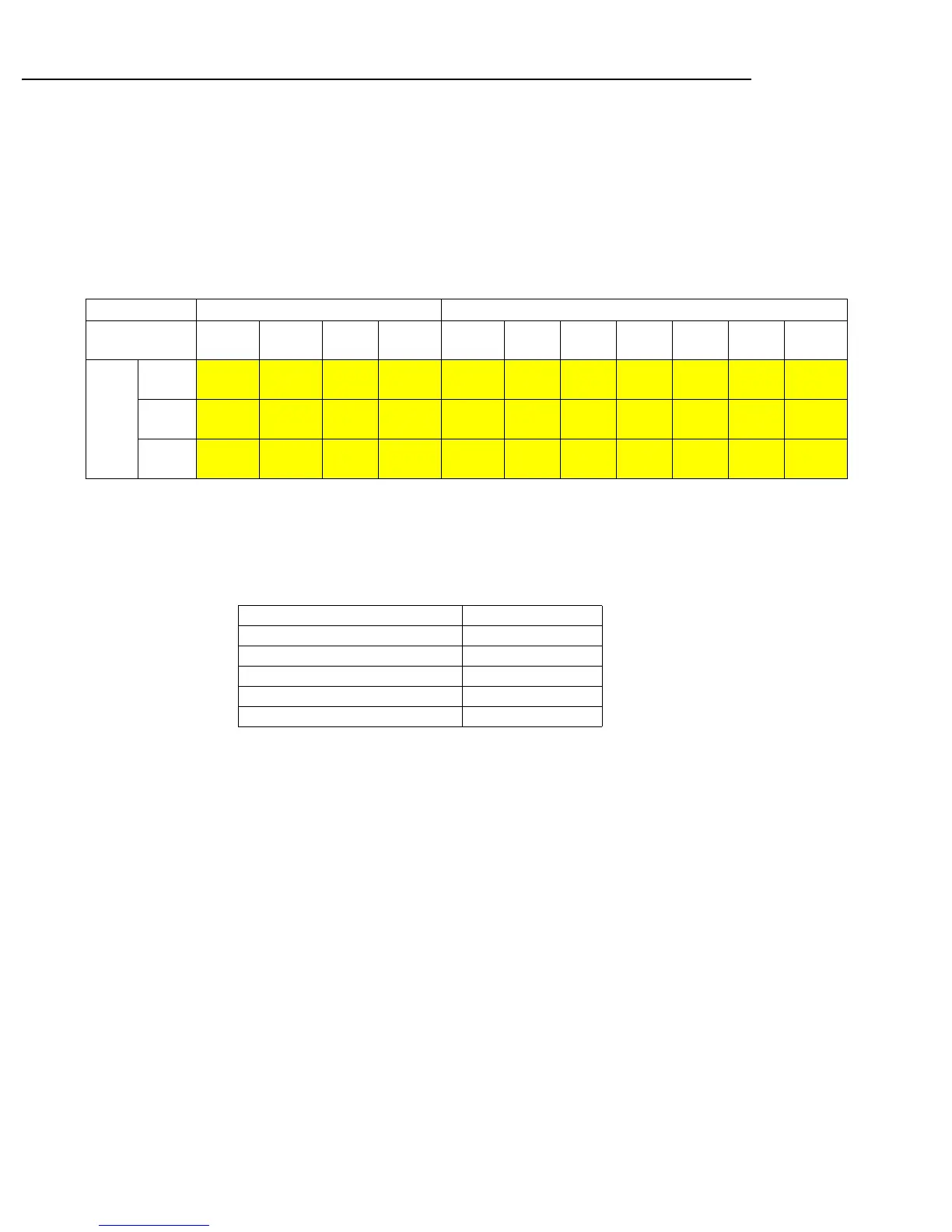
Table 4
1, 2, 3 b, c, d
ATE Mode Test
Frequencies (MHz)
H7 K7 M7 M10 P11 Q11 R10 R11 R12 JB T10
1 Flow b 536.000 589.500 662.000 674.000 702.000 740.000 799.700 770.000 794.000 806.000 854.000
2 Fmid c 542.000 594.500 668.000 681.500 708.000 746.000 806.000 777.000 799.700 808.000 859.500
PG4
3 Fhigh d 548.000 602.000 674.000 686.000 714.000 751.700 812.000 781.700 806.000 809.850 864.800
 Loading...