3
25A1104 (Rev.1)
CIRCUIT DESCRIPTION
General block diagram description.
The receiver consists of the following components: Image filters, predictive diversity circuitry, down-converter, first IF strip, SAW filter,
second mixer, second IF strip, ceramic filter, detector, RSSI buffer, low pass filter, RMS detector and expander, mute circuit, balanced and
unbalanced audio outputs, tonekey detection circuit, noise squelch circuit, microprocessor and several voltage regulators. The PG4 receiver
has two internal antennas mounted to the circuit board via antenna connectors..
RF Strip
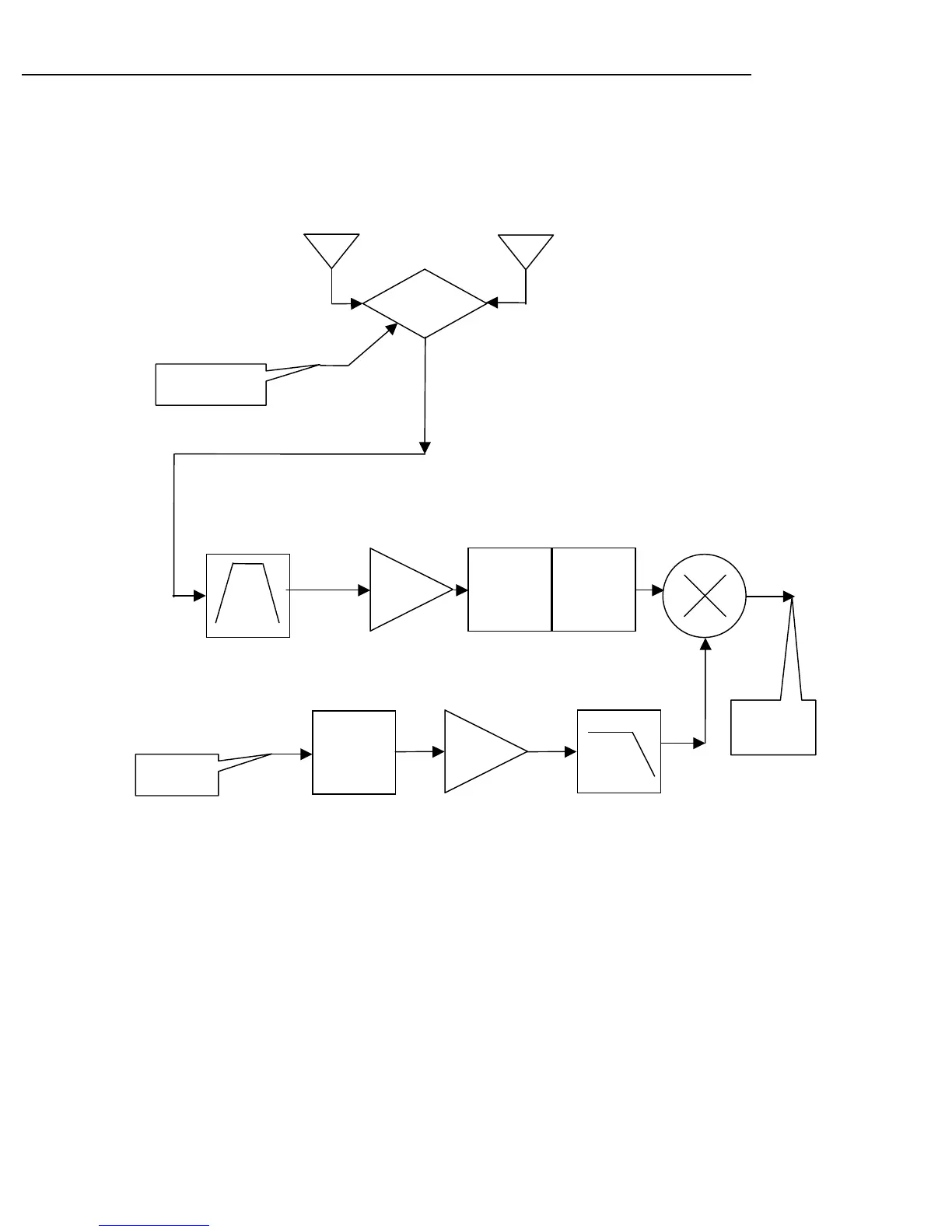
The receiver incorporates Shure's patented Predictive Diversity scheme. The microprocessor's A/D input is continuously monitoring buff-
ered RSSI output from the TP_RSSI_A2D test point. It uses a dynamically adaptive threshold to control dual PIN diode D510, to switch
between the internal antennas. The received RF signal enters an image rejection helical filter (FL510). The filter FL510 in conjunction with
a discrete filter post LNA attenuates the 1st LO frequency from reaching the antenna ports. The RF signal is then down-converted with
IC520, an integrated receiver front-end chip that includes: LNA (low noise amplifier), a GaAs FET mixer, and an IF buffer stage. The 50-
Ohm impedance of the mixer output's buffer stage is matched to the SAW filter FL600. The signal enters the 1st first IF amplifier, which
consists of Q603, and then it is filtered via a secondary LC filter comprised of C533, L523, C607, and C608. The second mixer is part of
IC610, which also contains the 2nd IF amplifier, limiter, FM detector, and wide dynamic range RSSI circuitry. The second mixer down-con-
verts the first IF signal (110.6 MHz) down to the second IF frequency of 10.7 MHz. The second IF signal is filtered with 10.7MHz ceramic
filters FL620 and FL625 and then demodulated with IC610 and quadrature coil L610. The audio output from the detector chip is injected to
an adjustable audio gain stage and also to the noise squelch stage. The RSSI output from the detector chip is connected to an input of the
A/D converter of the microprocessor for control of the predictive diversity circuit.
Buffer
LNA
1
st
MIXER
Helical
Filter
HPF for
lowside
injected
1
st
LO
LPF for
highside
injected
1
st
LO
1
st
LO
LPF
VCO
From µP
Controller
Internal Antenna A
Internal Antenna B
Predictive Diversity
From
microcontroller
PIN
Diode
Switch
To SAW
filter
 Loading...