5 Mounting
Mount the sensor and the reflector using suitable mounting brackets (see the SICK
range of accessories). Align the sensor and reflector with each other.
Note the sensor's maximum permissible tightening torque of 0.65 Nm.
6 Electrical installation
Operation in standard I/O mode:
The sensors must be connected in a voltage-free state (U
V
= 0 V). The following informa‐
tion must be observed, depending on the connection type:
– Plug connection: note pin assignment
– Cable: wire color
Only apply voltage/switch on the voltage supply (U
V
> 0 V) once all electrical connec‐
tions have been established.
Operation in IO-Link mode: Connect the device to a suitable IO-Link master and inte‐
grate in the master or control via IODD/function block. The green LED indicator flashes
on the sensor. IODD and function block are available to download from www.sick.com
under the part number.
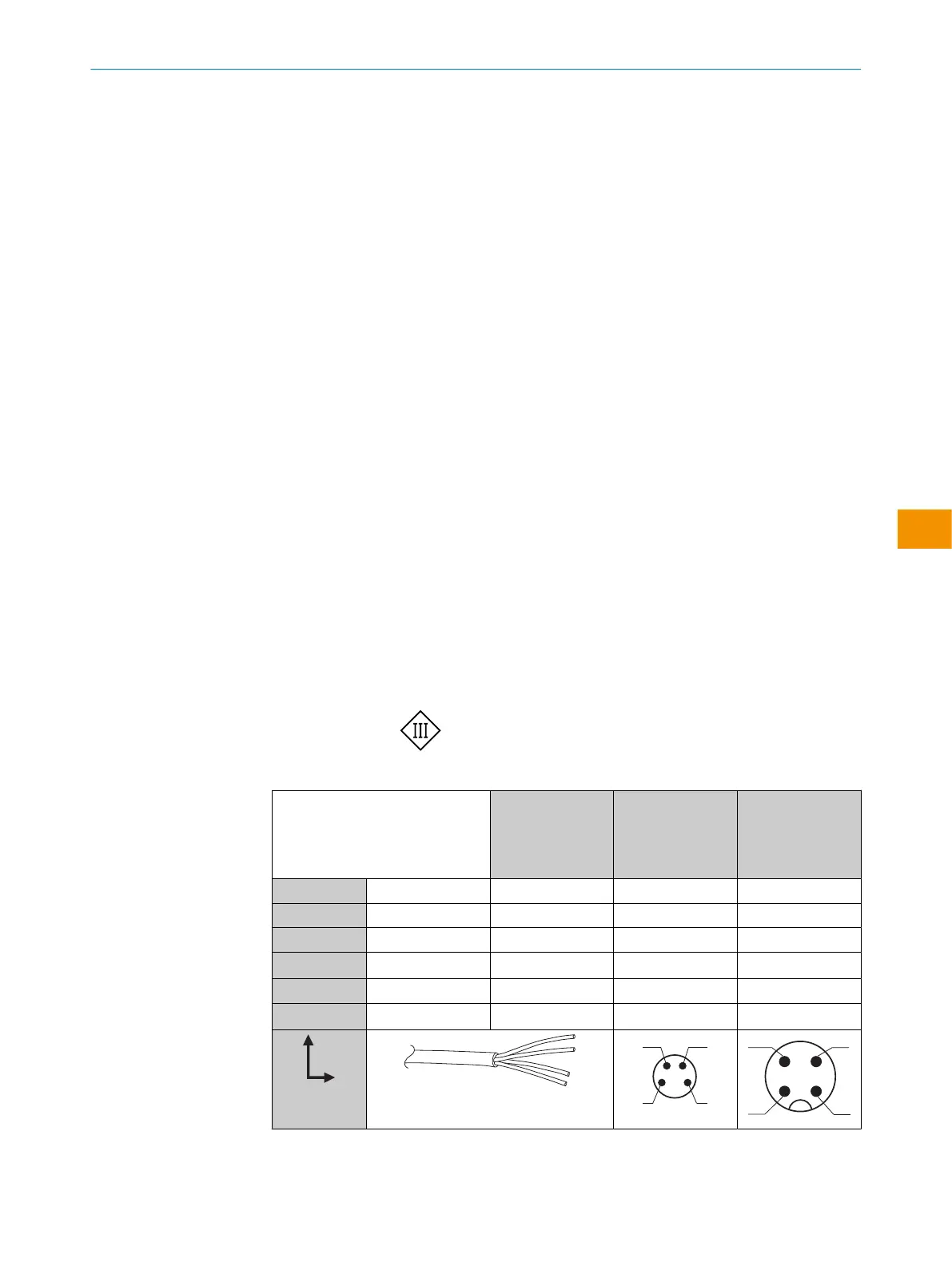
Explanation of the connection diagram (Tables 1-4):
Alarm = alarm output (see table 3 and table 7)
MF = multifunctional, programmable output
n. c. = not connected
QL1/C = switching output, IO-Link communication
U
B
: 10 ... 30 V DC, see "Technical data", page 33
Table 11: RAY10 with IO-Link
RAY10
-AB1xxxA00
-AB3xxxA00
-AB5xxxA00
-AB4xxxA00
1 BN + (L+) + (L+) + (L+)
2 WH MF MF MF
3 BU - (M) - (M) - (M)
4 BK Q
L1
/C Q
L1
/C Q
L1
/C
Default: MF
Q Q Q
Default Q
L1
/C Q Q Q
0.14 mm
2
AWG26
MOUNTING 5
8022198.1BXN / 2021-05-26 | SICK O P E R A T I N G I N S T R U C T I O N S | RAY10
23
Subject to change without notice
en
 Loading...