2
2687
12 2020
-
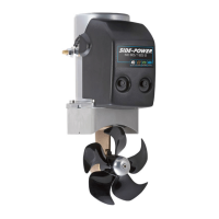
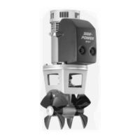
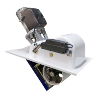
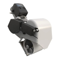
SE80 & SE100 & SE120 & SE130 & SE150
DECLARATION OF CONFORMITY
Sleipner Motor AS
P.O. Box 519, Arne Svendsensgt. 6-8
N-1612 Fredrikstad, Norway
Declare that this product with accompanying standard control systems complies with
the essential health and safety requirements according to:
DIRECTIVE 2013/53/EU
DIRECTIVE 2014/30/EU
DIRECTIVE 2014/35/EU
MC_0020
Contents
EN
Bow Installation Instructions
Bow Installation Considerations and Precautions ..................... 3
Thruster Measurements .......................................................... 4
Thruster Specications .............................................................. 5
Technical Specications .......................................................... 5
Positioning of the tunnel / thruster ............................................. 6
Tunnel Length ............................................................................ 7
Tunnel installation in sailboats ................................................... 8
Water Deection ........................................................................ 9
Tunnel ends ............................................................................. 10
Tunnel installation ............................................................. 11 - 12
Stern tunnel installation ........................................................... 13
Thruster Installation Instructions
Thruster Installation Considerations and Precautions ............. 14
Gear Leg & Motor Bracket Installation..................................... 15
Propeller Installation ................................................................ 16
Motor Installation ..................................................................... 17
Thruster Electrical Installation ................................................. 18
Electrical Specications .......................................................... 19
Control Panel Cable Installation ............................................. 20
Visual Wiring Diagram ............................................................ 21
Technical Wiring Diagram ....................................................... 22
Control Panel Installation ........................................................ 23
Pre-delivery Checklist .......................................................... 24
Spare Parts ............................................................................ 25
Warranty statement .............................................................. 25
MC_0031
Bow Installation Considerations and Precautions
EN
• The thruster must NOT be installed in compartments that require ignition proof electric equipment. If necessary, make a separate compartment.
(NB: Ignition Protected systems are tested to be installed in areas with possible explosive gases in accordance with ISO 8846)
• The electromotor will generate some carbon dust so any storage compartments must be separated from the thruster to prevent nearby items
becoming dusty/ dirty. (NB: IP version motors generate dust but are enclosed.)
• When installing the thruster electromotor in small compartments, ensure the compartment is well ventilated to allow for cooling of the electromotor.
• If the height of the room you are installing the thruster is limited, the thruster can be installed horizontally or at any angle in-between.
- If the electromotor is positioned more than 30º off vertical, it must be supported separately.
- Beware of keeping installation within advised measurements. No part of the propeller or gear house must be outside the tunnel.
• Do not install the thruster in a position where you need to cut a stiff ener/ stringer/ support that may jeopardise the hull integrity without checking with
the boat builder this can be done safely.
• The electromotor, components and cables must be mounted so they remain dry at all times.
• We advise painting the gear house and propellers with antifouling. (NB: Do not paint the anodes, sealings, rubber fi ttings or propeller shafts)
• Do not nish the inside of the tunnel with a layer of gelcoat/ topcoat or similar. There is only room for a thin coat of primer and two layers of anti-fouling
between the tunnel and the props.
• Don’t install the electromotor close to easily ammable objects or equipment as it will reach over 100°C before the temperature switch is activated.
• Do not store items close to the thruster motor. Any loose items near the thruster motor cis a potential re hazard and can cause undesired short-
circuiting.
Products
SE150/215T-24V - SE150 Tunnel thruster, 24V
SE150/215T-24 - SE150 Tunnel thruster, 24V
SE130/250T-24V - SE130 Tunnel thruster, 24V
SE130/250T-12V - SE130 Tunnel thruster, 12V
SE120/215T-24 - SE120 Tunnel thruster, 24V
SE120/215T-24V - SE120 Tunnel thruster, 24V
SE100/185T-24V - SE100 Tunnel thruster, 24V
SE100/185T-12V - SE100 Tunnel thruster, 12V
SE80/185T-24V - SE80 Tunnel thruster, 24V
SE80/185T-12V - SE80 Tunnel thruster, 12V

 Loading...