8
2687
12 2020
-
SE80 & SE100 & SE120 & SE130 & SE150
MG_0004
Min
Pos. B
Pos. A
1
1
2
3
4 65
MG_0048
Increase tunnel length to protect
the propeller from water forces
when high-speed cruising.
Water
Forces
Increase tunnel length to prevent
a circular water vacuum cavity
between the propeller and the
hull of the boat.
STANDARD USE FLAT BOTTOM HULL HIGH-SPEED OPERATION
Do not allow the variable length of the tunnel walls to vary in length
excessively.
EG. the top tunnel wall is x 4 longer than the bottom wall.
Cavitation
Water flow must have
space to "straighten"
itself for best
performance.
The gear leg/ propeller(s) must
never extend out of the tunnel
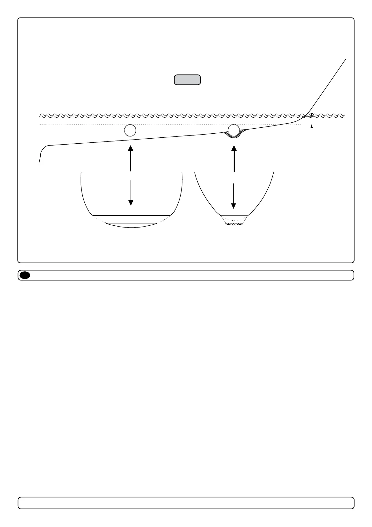
Tunnel installation in sailboats
EN
Some sailboats have a at bottom and shallow draft in the bow section. This can make installing the thruster as far forward from the boats main pivot
point diffi cult. (Fig. 1).
However, it is possible to install a tunnel thruster in most sailboats, even when the hull does not directly support the tting of a tunnel.
Instead t the tunnel halfway into the underneath section of the existing hull. Strengthen it with a de ector/ spoiler directing the water ow around the
tunnel. This will allow installation of the thruster in the proper position on the boat, maintaining the reliability and space advantages of the tunnel thruster.
This installation is being used by some of the world’s largest sailboat builders and has proven to give little to no speed loss during normal cruising. This
can also be an installation method for at bottomed barges to avoid extremely long tunnels and large oval tunnel openings in the hull.
MC_0003

 Loading...