© Siemens plc 1999 | G85139-H1731-U400-D2 9
Control Cable Connections
CAUTION
The control and power supply cables must be laid separately. They must not be fed
through the same cable conduit / trunking.
Use screened cable for the control lead.
Feed the control cable into the inverter via
the appropriate gland hole . Connect the
control wires in accordance with the
information in Figures 4,5 and 6 having first
unplugged connector block PL800 from the
PCB (CS B only).
IMPORTANT: A wire link must be fitted
between control terminals 5 (DIN1) and 1
(P10+) if it is required to start the inverter
from the control potentiometer R314, or the
analogue input. The wire link must be
removed when operation via a run/stop
switch is required.
Note that the optional potentiometer fitted as
an analogue set point shown in Figure 4
assumes that jumper JP304 is connecting 0V
(pin 2) to AIN- (pin 4).
Also, +15V can be used as an alternative to
P10+ for the digital inputs.
Plug the connector block back into the PCB
(CS B only), refit the cover and tighten the
four securing screws.
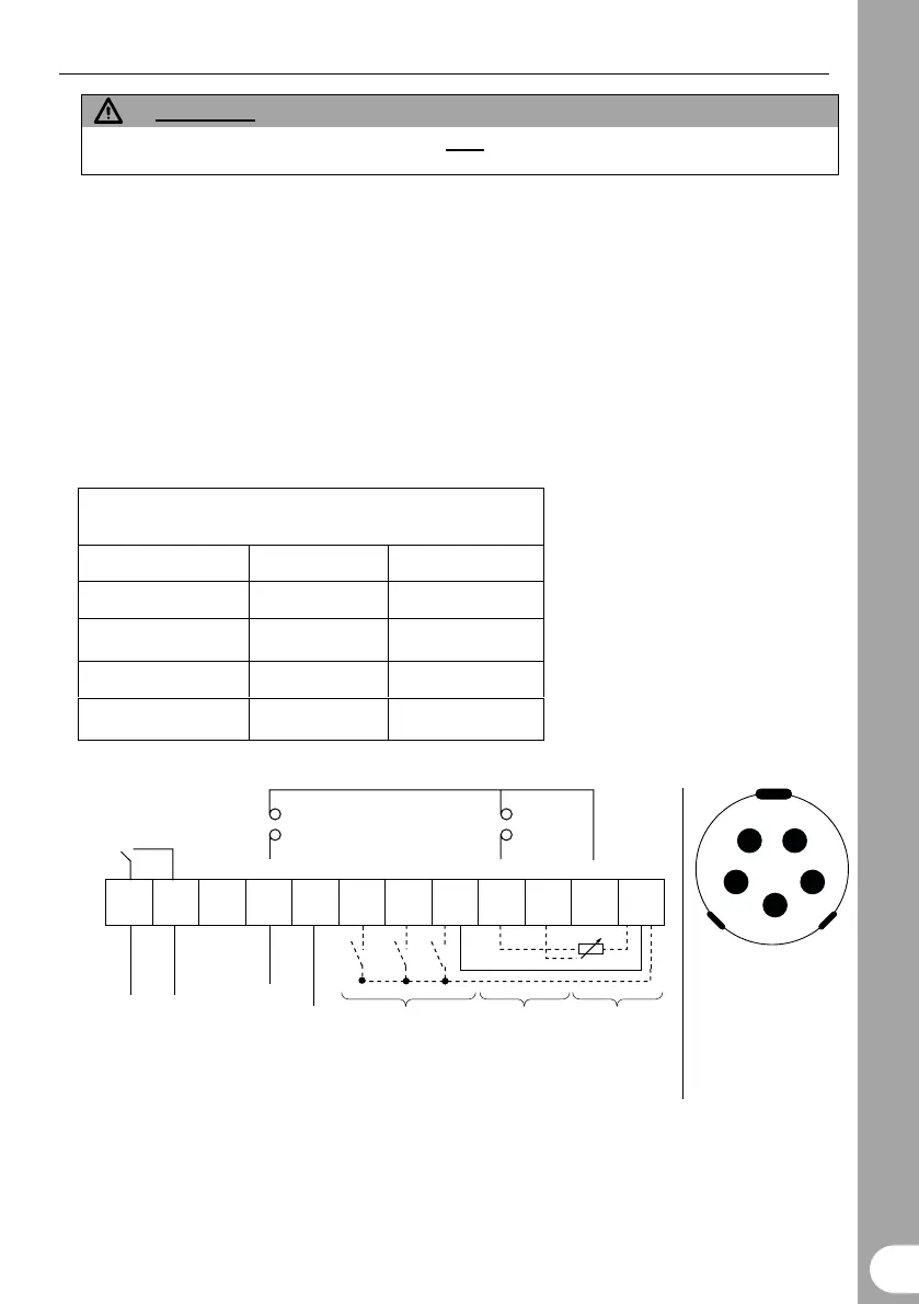
COMBIMASTER Control Terminals
Cabling Information
CS A (PL700): CS B (PL800)
Cable AWG 22 - 18 28 – 20
= approx. mm
2 0.35 – 0.82 0.08 – 0.50
Strip length (mm) 5 – 6 5 – 6
Strip length (inch) 0.22 0.22
12 11 10 9 8 7 6 5
5
4
4
3
3
2
2
1
1
PI+ PI- +15V
JP305 JP304
1 - +5V (250mA max.)
2 - N (-)
3 - 0V
4 - P (+)
5 - no connection
PI Power Supply
(+15V,
max. 50mA)
PI +ve Input
(0 - 10V
or 0 - 20mA)
RLB
(NO)
RLC
(COM)
Relay (RL1)
(30V dc. 1.0 A max.)
Digital Inputs
(7.5 - 33V, max. 5mA)
PL800 (CS B) / PL700 (CS A) SK200 Socket
DIN3 DIN2 DIN1 AIN- AIN+ 0V P10+
Analogue Input
(0/2 - 10V,
or 0/4 - 20mA)
Power Supply
for Digital and
Analogue
Inputs
(+10V, max. 10mA)
PI -ve Input
Figure 4 Control Terminal Connections