© Siemens plc 1999 | G85139-H1731-U400-D2 5
Poor running characteristics can arise in
cases where the transmission elements have
a length ratio of hub length to shaft end
length < 0.8 and they run at speeds greater
than 1500 rpm. In such cases rebalancing
may be necessary, e.g. by reducing the
distance by which the featherkey protrudes
from the transmission element and the shaft
surface.
Please check the following prior to
commissioning:
• The rotor turns freely without rubbing.
• The motor is assembled and aligned
properly.
• The transmission elements are adjusted
correctly (e.g. belt tension) and the
transmission element is suitable for the
given operating conditions.
• All electrical connections, mounting
screws and connecting elements are
tightened and fitted correctly.
• All protective conductors are installed
properly.
• Any auxiliary equipment that might be
fitted (e.g. mechanical brake) is in
working order.
• Protection guards are installed around all
moving and live parts.
• The maximum speed (see motor rating
plate) is not exceeded. The maximum
speed is the highest operating speed
permitted. Remember that motor noise
and vibration are worse at this speed
and bearing life is reduced.
The above list is not meant to be exhaustive
- additional checks may also be required.
Mechanical Installation | MICROMASTER Integrated
The motor / MICROMASTER Integrated
combination should be installed according to
guidelines similar to those given above for
the COMBIMASTER.
First fit the Motor Interface Plate (MIP) to the
motor. In most cases the MIP makes use of
the existing motor gasket. Refer to Siemens
Document ‘MMI Motor Adaptation
Guidelines’ (English) – (Available 2
nd
Qtr
1999.– G85139-H1731-U500-A1.
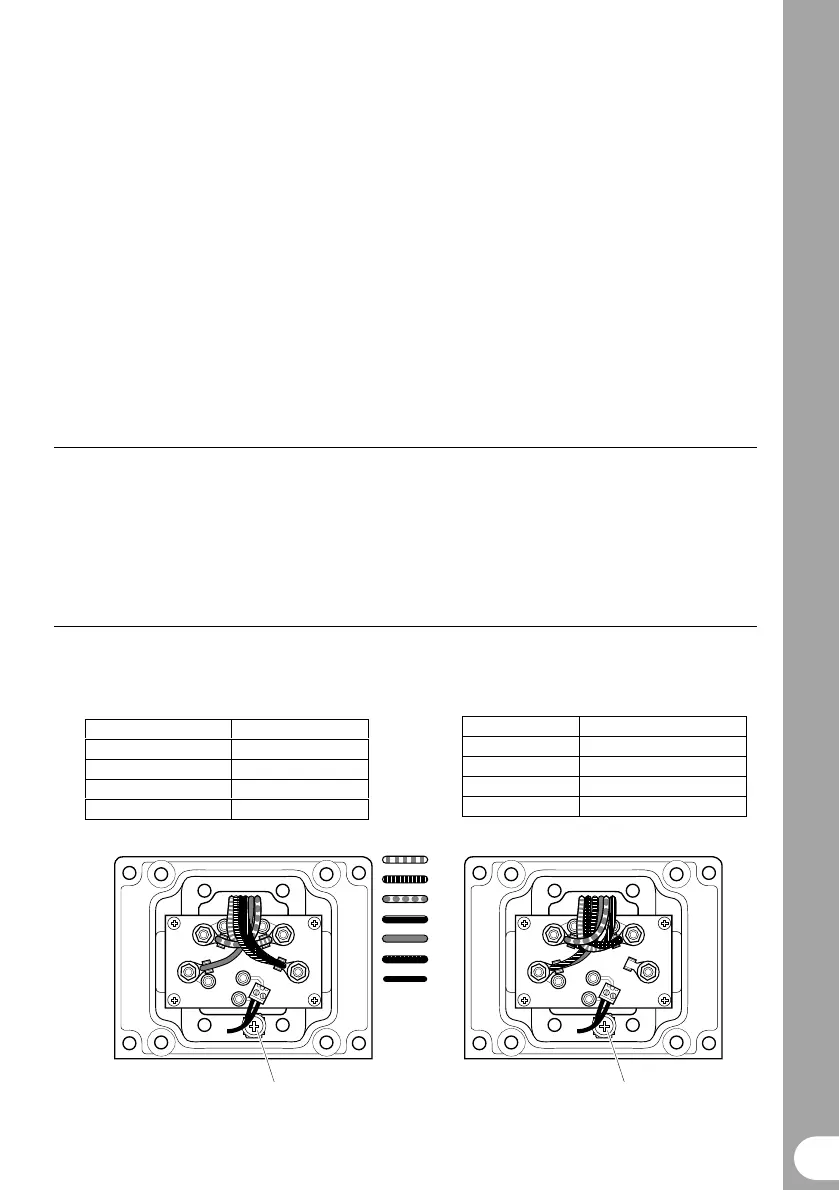
Electrical Installation | MICROMASTER Integrated
The motor wires should be connected in
either star or delta configuration on the MIP
Star Connection
Wire Terminal
U2/V2/W2 N
U1 U
V1 V
W1 W
(check motor rating plate).
Delta Connection
Wire Terminal
U1/W2 U
U2/V1 V
V2/W1 W
W
V
U
N
TB1
W
V
U
N
TB1
U1
U2
V1
V2
W1
W2
PTC
wires
Earth connection
Star connection Delta connection
Earth connection
Figure 1 Motor Wire Connection
 Loading...