© Siemens plc 1999 | G85139-H1731-U400-D2 13
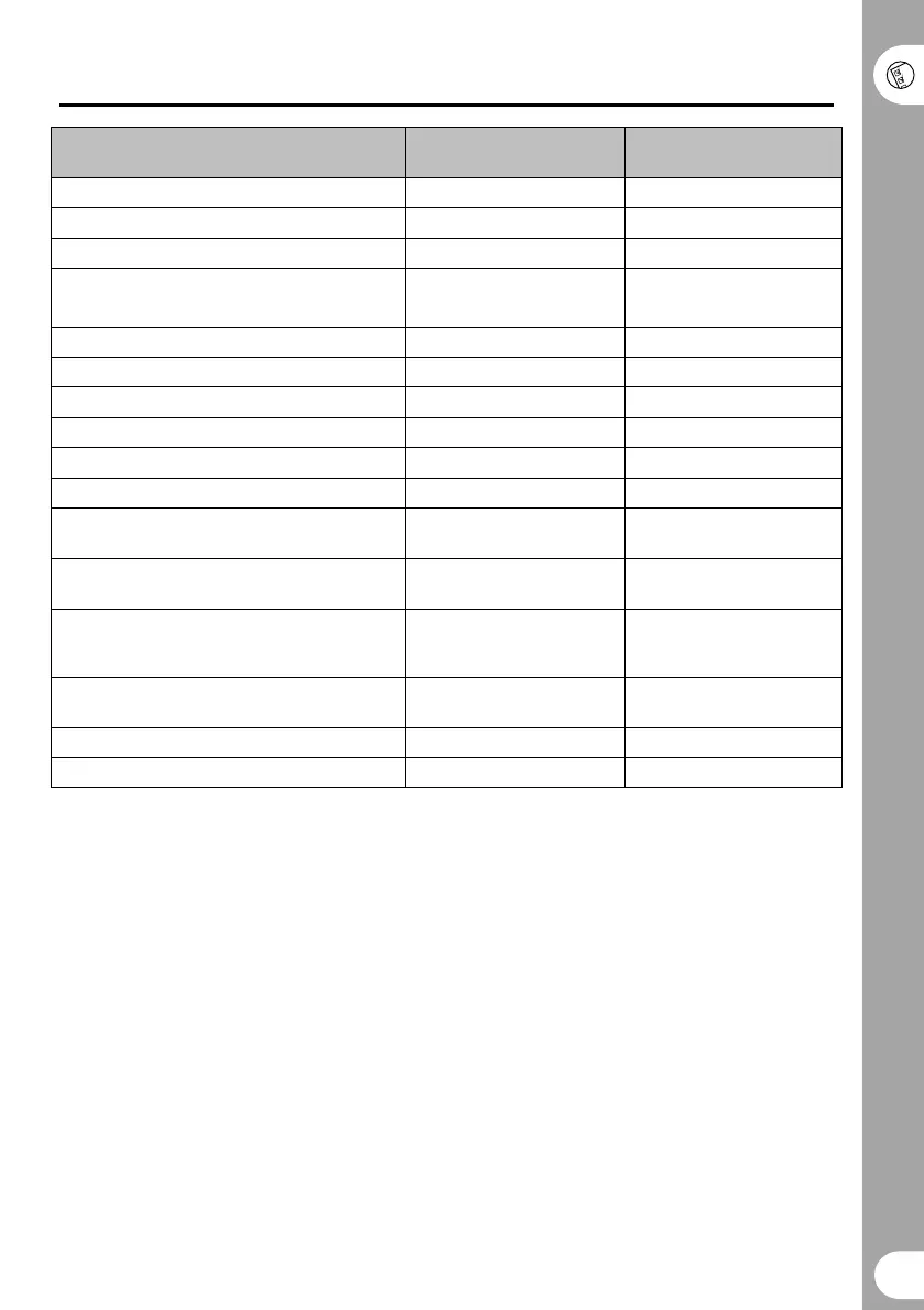
OPTIONS / ACCESSORIES
Description: Order Number: Shortcode:
(for ordering with unit)
Clear Text Display (OPm2) 6SE3290-0XX87-8BF0
Interface cable for OPm2 - 3m screened 6SE9996-0XA31
Reference Manual 6SE9996-0XA35
PROFIBUS Module (CB155)
Note : For CS B , Issue A units :
6SE9996-0XA18
use : 6SE9996-0XA20
PROFIBUS T-Connector 6SE9996-0XA21
PROFIBUS Terminator 6SE9996-0XA22
PROFIBUS Cable - 1m 6SE9996-0XA23
PROFIBUS Cable - 5m 6SE9996-0XA24
PROFIBUS Cable - 10m 6SE9996-0XA25
PROFIBUS Cable Link 6SE9996-0XA26
CS A Inverter Fan Option
(MICROMASTER Integrated only)
6SE9996-0XA01 M41
CS B Inverter Fan Option
(MICROMASTER Integrated only)
6SE9996-0XA02 M41
CS A Electro-mechanical Brake Control
Unit
(Note :Expected Product release: August
1999)
6SE9996-0XA07
CS B Electro-mechanical Brake Control
Unit
6SE9996-0XA10
CS B Pulse Resistor Braking Unit 6SE9996-0XA11
SIMOVIS PC Software 6SE3290-0XX87-8SA2
Note:
CS A covers power range 120W to 1.5kW
CS B covers power range 1.5kW to 7.5kW
 Loading...