CPU 31x-2 as DP Master/DP Slave and Direct Communication
2-24
PLC S7-300, CPU Specifications CPU 312 IFM to CPU 318-2 DP
A5E00111190-01
2.6.4 Format of the Slave Diagnostic Data
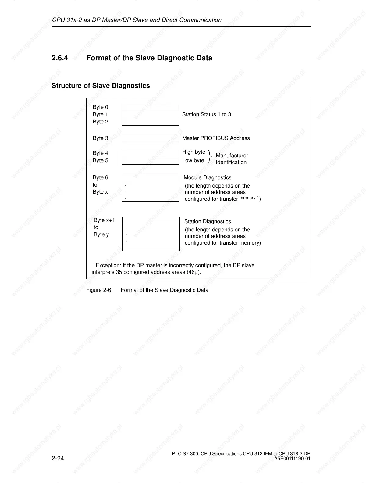
Structure of Slave Diagnostics
Byte 0
Byte 1 Station Status 1 to 3
Byte 2
Byte 3 Master PROFIBUS Address
Byte 4
Byte 5 Low byte
High byte
Manufacturer
Identification
Byte 6
to
Module Diagnostics
Byte x
Station Diagnostics
.
.
.
.
.
.
Byte x+1
to
Byte y
(the length depends on the
number of address areas
configured for transfer
memory
1
)
(the length depends on the
number of address areas
configured for transfer memory)
1
Exception: If the DP master is incorrectly configured, the DP slave
interprets 35 configured address areas (46
H
).
Figure 2-6 Format of the Slave Diagnostic Data
 Loading...


