CPUs
1-57
PLC S7-300, CPU Specifications CPU 312 IFM to CPU 318-2 DP
A5E00111190-01
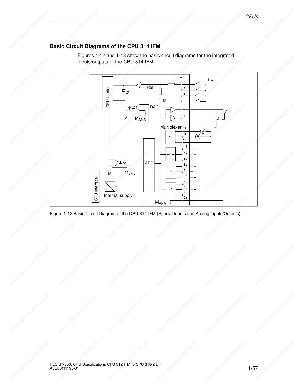
Basic Circuit Diagrams of the CPU 314 IFM
Figures 1-12 and 1-13 show the basic circuit diagrams for the integrated
inputs/outputs of the CPU 314 IFM.
L +
DAC
Internal supply
+
Ref
M
ADC
V
A
M
ANA
M
ANA
Multiplexer
V
A
M
ANA
CPU interface
CPU interface
M
M
Figure 1-12 Basic Circuit Diagram of the CPU 314 IFM (Special Inputs and Analog Inputs/Outputs)
 Loading...


