CPUs
1-22
PLC S7-300, CPU Specifications CPU 312 IFM to CPU 318-2 DP
A5E00111190-01
1.3.2 Diagnostics with LED Display
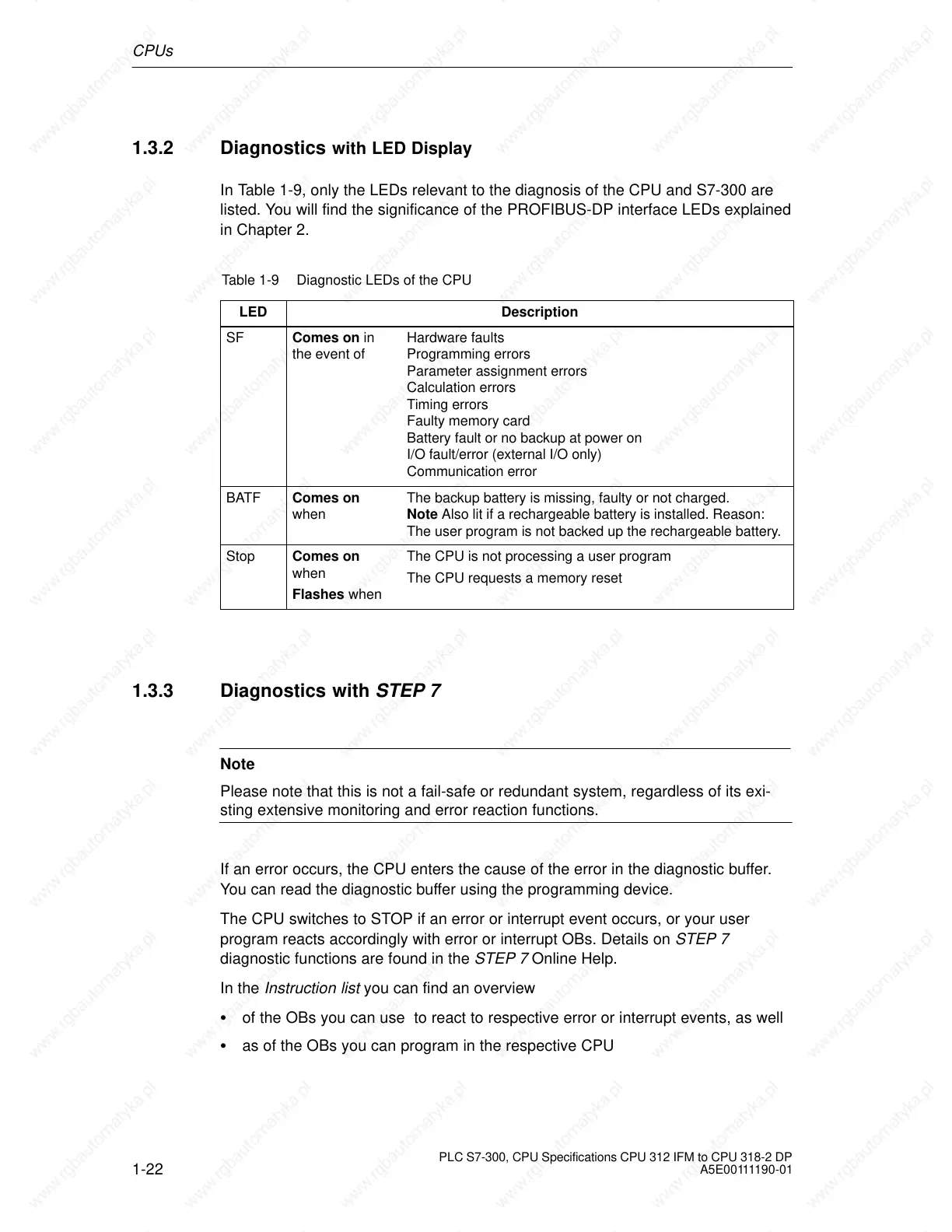
In Table 1-9, only the LEDs relevant to the diagnosis of the CPU and S7-300 are
listed. You will find the significance of the PROFIBUS-DP interface LEDs explained
in Chapter 2.
Table 1-9 Diagnostic LEDs of the CPU
LED
Description
SF Comes on in
the event of
Hardware faults
Programming errors
Parameter assignment errors
Calculation errors
Timing errors
Faulty memory card
Battery fault or no backup at power on
I/O fault/error (external I/O only)
Communication error
BATF Comes on
when
The backup battery is missing, faulty or not charged.
Note Also lit if a rechargeable battery is installed. Reason:
The user program is not backed up the rechargeable battery.
Stop Comes on
when
Flashes when
The CPU is not processing a user program
The CPU requests a memory reset
1.3.3 Diagnostics with STEP 7
Note
Please note that this is not a fail-safe or redundant system, regardless of its exi-
sting extensive monitoring and error reaction functions.
If an error occurs, the CPU enters the cause of the error in the diagnostic buffer.
You can read the diagnostic buffer using the programming device.
The CPU switches to STOP if an error or interrupt event occurs, or your user
program reacts accordingly with error or interrupt OBs. Details on STEP 7
diagnostic functions are found in the STEP 7 Online Help.
In the Instruction list you can find an overview
of the OBs you can use to react to respective error or interrupt events, as well
as of the OBs you can program in the respective CPU
 Loading...


