Cycle and Reaction times
3-15
PLC S7-300, CPU Specifications CPU 312 IFM to CPU 318-2 DP
A5E00111190-01
Diagnostic Interrupt Response Times of the CPUs
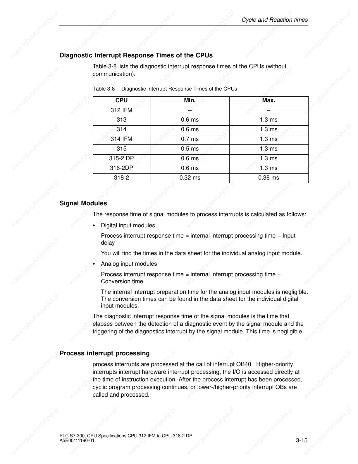
Table 3-8 lists the diagnostic interrupt response times of the CPUs (without
communication).
Table 3-8 Diagnostic Interrupt Response Times of the CPUs
CPU Min. Max.
312 IFM – –
313 0.6 ms 1.3 ms
314 0.6 ms 1.3 ms
314 IFM 0.7 ms 1.3 ms
315 0.5 ms 1.3 ms
315-2 DP 0.6 ms 1.3 ms
316-2DP 0.6 ms 1.3 ms
318-2 0.32 ms 0.38 ms
Signal Modules
The response time of signal modules to process interrupts is calculated as follows:
Digital input modules
Process interrupt response time = internal interrupt processing time + Input
delay
You will find the times in the data sheet for the individual analog input module.
Analog input modules
Process interrupt response time = internal interrupt processing time +
Conversion time
The internal interrupt preparation time for the analog input modules is negligible.
The conversion times can be found in the data sheet for the individual digital
input modules.
The diagnostic interrupt response time of the signal modules is the time that
elapses between the detection of a diagnostic event by the signal module and the
triggering of the diagnostics interrupt by the signal module. This time is negligible.
Process interrupt processing
process interrupts are processed at the call of interrupt OB40. Higher-priority
interrupts interrupt hardware interrupt processing, the I/O is accessed directly at
the time of instruction execution. After the process interrupt has been processed,
cyclic program processing continues, or lower-/higher-priority interrupt OBs are
called and processed.
 Loading...


