Description, technical data
2.7 Definitions of the electrical data
A5E01083943A AB
Siemens AG Operating Instructions 2.02 1FW4
29
2.7 Definitions of the electrical data
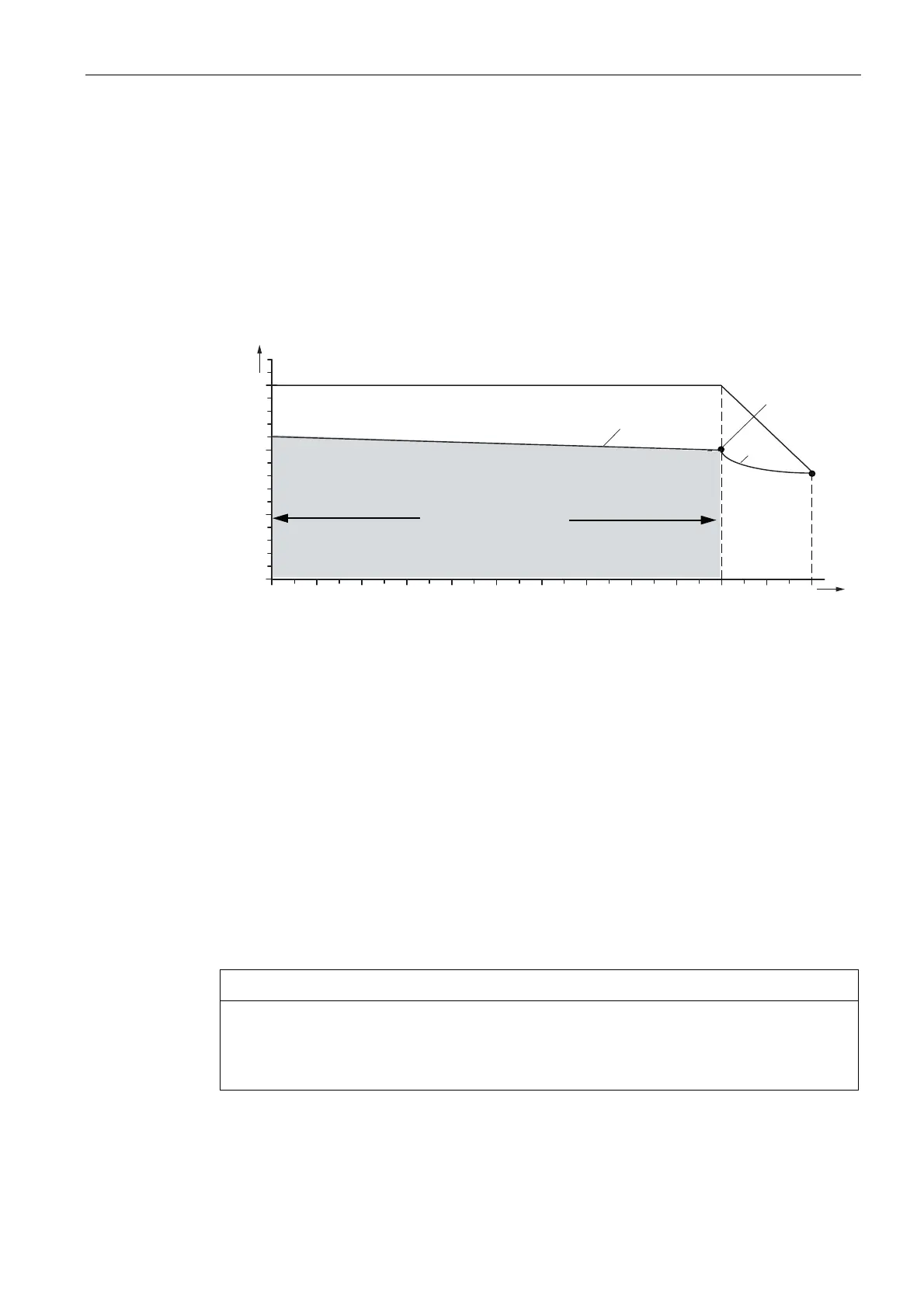
Torque-speed characteristic
The layout of the converter and of the motor determines the overload capacity of the motor-
converter system. You can find more detailed information on this in the SINAMICS catalogs.
The 1FW4 motors can be briefly overloaded up to 1.5 times the rated torque. The available
base load current of the converter is reduced by overload demands. This can require the
selection of a larger converter. The following limiting characteristics always apply for all
motor and SINAMICS converter module combinations.
5DWHGSRLQW
%DVHVSHHGUDQJH
)LHOG
ZHDNHQLQJ
UDQJH
6GXW\
0
0
PD[
00
1
QQ
1
Q
3 NRQVW
M
: Torque
M
max
: Maximum torque
M/M
N
: Torque/rated torque
M
N
: Rated torque
S1-duty: Continuous Duty
P = const. : Constant power
n
N
: Rated speed
n/n
N
: Speed/rated speed
Figure 2-5 Speed-torque characteristic for 1FW4 motors
Voltage limiting characteristics
As the speed of the permanent-magnet rotor increases, the counter-voltage of the motor that
is induced in the terminals increases to the same degree. The difference between the DC
link voltage of the converter and the increasing motor counter-voltage can be used to apply
the current. This limits the magnitude of the current which can be applied at high speeds.
CAUTION
Damage to the insulation
Continuous duty above the S1 characteristic is not thermally permitted for the motor. The
insulation can get damaged. - Also see Figure "Rotation-to-speed characteristic of the
synchronous motors".
 Loading...